YSie fertigen eine Blechhalterung in SolidWorks, exportieren die native .SLDPRT-Datei, und senden sie an einen Auftragsfertiger zur Angebotserstellung. Einige Stunden später kommt eine E-Mail: “Wir können diese Datei nicht öffnen. Können Sie stattdessen eine STEP- oder DXF-Datei bereitstellen?”
Dieses Szenario spielt sich täglich in Engineering- und Beschaffungsteams ab. Die Ursache ist kein technischer Fehler – es ist eine Formatinkompatibilität. Jede CAD-Software speichert Dateien in ihrer eigenen proprietären Struktur, und die meisten Hersteller verwenden andere Software als ihre Kunden. Eine Datei, die auf Ihrem Bildschirm einwandfrei geöffnet wird, kann auf der anderen Seite unlesbar sein.
Das Verständnis von CAD-Dateiformaten ist nicht nur eine technische Neugierde. Für Ingenieure und Einkäufer, die mit externen Herstellern zusammenarbeiten, die Vorbereitung einer vollständigen Blech-RFQ– einschließlich des richtigen CAD-Formats – wirkt sich direkt darauf aus, wie schnell Sie ein Angebot erhalten und wie genau Ihre Teile gefertigt werden.
Was ist eine CAD-Datei?
Eine CAD-Datei ist ein digitales Dokument, das von Computer-Aided-Design-Software erstellt wird und die Geometrie, Abmessungen und Konstruktionsparameter eines Bauteils oder einer Baugruppe speichert. Ingenieure und Konstrukteure verwenden CAD-Dateien, um zu definieren, wie ein Bauteil vor der Fertigung aussieht.
CAD-Dateien fallen in zwei grobe Kategorien. 2D-CAD-Dateien enthalten flache Zeichnungen – Konturen, Abmessungen und Anmerkungen, die typischerweise für die Konstruktion und Werkstattdokumentation verwendet werden. 3D-CAD-Dateien enthalten Volumen- oder Oberflächenmodelle, die die vollständige Geometrie eines Bauteils in drei Dimensionen darstellen. Moderne Blechfertigungs-Workflows stützen sich stark auf 3D-Modelle für die Programmierung von CNC-Maschinen, Laserschneidern und Abkantpressen, während 2D-Zeichnungen nach wie vor das primäre Medium für die Übermittlung von Toleranzen, Materialien und Oberflächenanforderungen sind.
Drei Arten von CAD-Dateiformaten

Ein klares technisches Vergleichsdiagramm mit drei Spalten mit den Bezeichnungen “Native”, “Exchange” und “Mesh”, jeweils mit repräsentativen Dateiformat-Symbolen und einem Beispiel-3D-Modell, das den Detaillierungsgrad zeigt, den jedes Format beibehält.
Nicht alle CAD-Dateien sind austauschbar. Sie fallen in drei Kategorien, jede mit unterschiedlichen Kompromissen.
Native (proprietäre) Formate
Native Formate werden nur von der Software erstellt und gelesen, die sie erzeugt hat. Beispiele sind .SLDPRT (SolidWorks), .CATPart (CATIA), .IPT (Autodesk Inventor) und .DWG (AutoCAD). Diese Dateien behalten die vollständige Konstruktionshistorie bei – Feature-Bäume, parametrische Beziehungen und Skizzenbedingungen. Sie sind ideal für iterative Konstruktionsarbeit innerhalb einer einzigen Softwareumgebung.
Die Einschränkung ist offensichtlich: eine native Datei ist an ihre Stammsoftware gebunden. Wenn Ihr Hersteller nicht dieselbe CAD-Plattform verwendet, kann er sie nicht öffnen.
Austauschformate (neutrale Formate)
Austauschformate sind dafür konzipiert, 3D-Geometrie zwischen verschiedenen CAD-Systemen zu übertragen. Das am weitesten verbreitete ist .STEP (.stp oder .step), geregelt durch die Norm ISO 10303. STEP-Dateien übertragen vollständige 3D-Geometrie mit hoher Genauigkeit und sind damit der De-facto-Standard für den Austausch von Modellen mit externen Herstellern, Simulationstools und Lieferkettenpartnern.
.IGES (.igs) ist ein älteres Austauschformat, das noch in Legacy-Workflows zu finden ist. .DXF (.dxf), ursprünglich von Autodesk entwickelt, ist ein neutrales Format, das hauptsächlich für 2D-Profile verwendet wird und der Standard-Input für Laserschneid- und CNC-Stanzmaschinen ist.
Exchange formats sacrifice the parametric feature history—manufacturers see the final geometry but cannot edit individual features like a fillet or a hole pattern. For quoting and production, this is rarely a problem.
Mesh Formats
Mesh formats represent 3D surfaces as a collection of triangles. .STL is the most common mesh format, widely used in 3D printing and rapid visualization. .OBJ und .3MF serve similar purposes.
Mesh files are lightweight and universally readable, but they contain no engineering data—no dimensions, no tolerances, no material information. A mesh file tells a manufacturer the shape of a part, but nothing about how to make it.
| Format Type | Examples | Geometry Fidelity | Engineering Data | Parametric History |
|---|---|---|---|---|
| Native | .SLDPRT, .CATPart, .IPT, .DWG | Full | Full (within software) | Ja |
| Exchange | .STEP, .IGES, .DXF, .JT | Hoch | Partial (geometry only) | Nein |
| Mesh | .STL, .OBJ, .3MF | Surface only | Keine | Nein |
Gängige CAD-Dateiformate und ihre jeweiligen Funktionen
.DWG and .DXF — The 2D Drafting Standard
.DWG is AutoCAD’s native format and the most widely used file type for 2D engineering drawings. It stores lines, dimensions, hatching, and text annotations. While DWG is technically a native format, its ubiquity means most CAD software can read or import it.
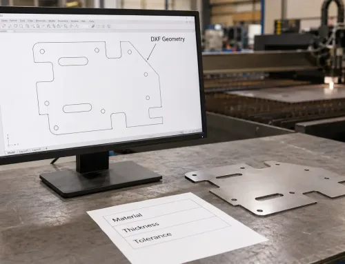
.DXF is the exchange equivalent of DWG—a neutral 2D format that any software can open. In sheet metal manufacturing, DXF files are the standard input for laser cutting, waterjet, and CNC punching because they carry clean 2D profiles that cutting machines can interpret directly.
.STEP — The Universal 3D Exchange Format
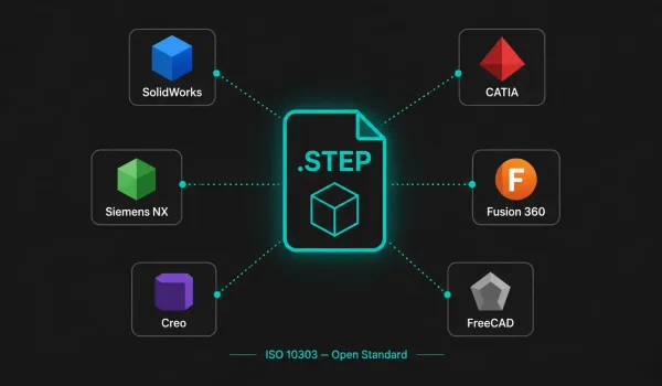
A diagram showing a single STEP file in the center connecting outward to multiple CAD software platforms, illustrating its role as a universal exchange format.
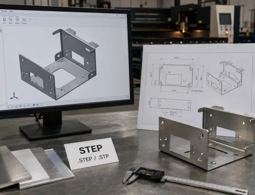
.STEP (.stp / .step) is the most important format for engineers sharing 3D models with external parties. Governed by ISO 10303, STEP is an open standard—not controlled by any single software vendor.
When you send a STEP file to a manufacturer, they can open it in SolidWorks, CATIA, Siemens NX, Fusion 360, or virtually any modern CAD system. The geometry transfers accurately. What you lose is the feature history and parametric relationships, but for manufacturing purposes, the final shape is what matters.
.IGES — The Legacy Exchange Format
.IGES (.igs) predates STEP and is still encountered in older supply chains, particularly in aerospace and defense. It transfers surface and wireframe geometry reliably but has known limitations with complex solid models.
If your customer or supplier specifically requests IGES, STEP is almost always a better alternative—ask whether they can accept STEP instead.
.STL — For 3D Printing, Not for Manufacturing
.STL files describe a surface as a mesh of triangles. They are the standard input for 3D printing and are useful for quick visual review.
However, STL files contain no dimensional data, no tolerances, and no material specifications. Sending an STL to a sheet metal manufacturer is like sending a photograph of a blueprint—it shows the shape but provides none of the information needed to produce the part.
.SLDPRT / .CATPart / .IPT — Software-Specific Formats
These native formats are the working files inside their respective CAD systems. They are the best choice when both you and your manufacturer use the same software, since they preserve the complete design intent.
In der Praxis, most cross-company workflows convert to STEP before sharing.
Was Sie einem Blechhersteller senden sollten
Why STEP + PDF Drawing Is the Best Combination for Quoting
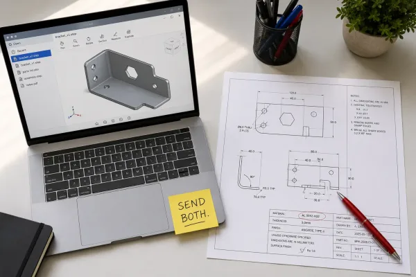
An overhead view of a desk showing a laptop screen displaying a STEP file in a CAD viewer, next to a printed PDF engineering drawing with annotations, representing the ideal file package for requesting a manufacturing quote.
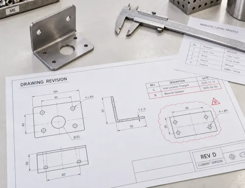
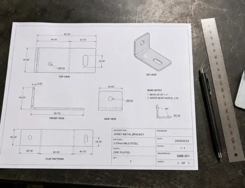
For most sheet metal quoting scenarios, the ideal submission is a STEP file of the 3D model paired with a 2D fabrication drawing in PDF format that specifies material, thickness, tolerances, surface finish, and any secondary operations (welding, tapping, plating).
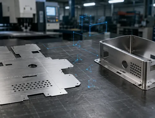
The STEP file gives the manufacturer the geometry they need to program laser paths, bend sequences, and fixture layouts. The PDF drawing gives them the engineering requirements the model alone cannot carry.
A STEP file without a drawing forces the manufacturer to make assumptions about material, tolerances, and finish—assumptions that often lead to clarification emails, delayed quotes, or parts that do not meet your expectations.
When DXF Is the Right Choice
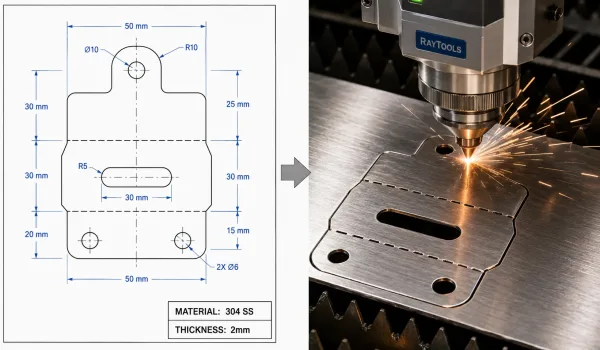
A split image showing a 2D DXF drawing of a flat sheet metal bracket profile on the left, and an industrial laser cutter actively cutting a metal sheet on the right, illustrating the direct workflow from DXF to production.
For flat-profile work—Präzisionslaserschneiden, waterjet cutting, or CNC punching—a 2D DXF file is often all that is needed. The DXF carries the cut profile, and the manufacturer pairs it with your specifications for material and thickness.
If your part only requires cutting (no bending, no welding, no assembly), DXF is simpler and more direct than a 3D model.
What the File Needs to Contain
Regardless of format, every file you send to a manufacturer should include or be accompanied by:
- Units — millimeters or inches. A model built in inches sent to a manufacturer working in millimeters will produce parts that are 25.4× the intended size.
- Materialspezifikation — not just “steel” but a specific grade (e.g., ASTM A36 cold-rolled steel, 304 stainless, 5052-H32 aluminum).
- Blechdicke — the nominal thickness of the raw material. For sheet metal, this is a critical dimension that affects bend calculations and structural performance.
Warum das Modell nicht die Fertigungsspezifikation ist
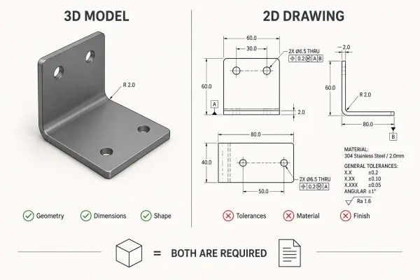
A side-by-side comparison showing a 3D CAD model of a sheet metal bracket on the left and a 2D engineering drawing with GD&T callouts, material specifications, and surface finish symbols on the right, demonstrating that both are needed for manufacturing.
A common misconception among first-time buyers is that the 3D model is the complete manufacturing instruction. It is not.
A CAD model defines geometry—the shape, size, and spatial relationships of features. It does not tell a manufacturer what material to use, what tolerances to hold, what surface finish to achieve, or how to handle sharp edges and weld seams.
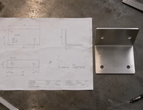
The manufacturing specification lives in the technical drawing for manufacturing. This is where GD&T (Geometric Dimensioning and Tolerancing), material callouts, surface roughness symbols, critical dimensions, and notes about finishing or inspection are recorded.
In a well-run manufacturing workflow, the model and the drawing work together: the model provides the shape, the drawing provides the requirements. Sending only a model is like giving someone a map without telling them the destination—they can see the roads but do not know where to go.
Wie Sie CAD-Dateien ohne AutoCAD öffnen und anzeigen können
Not everyone who receives a CAD file needs—or can afford—a full CAD license. For buyers, project managers, and quality inspectors who only need to view, measure, or annotate a model, free viewers are widely available.
Autodesk Viewer (viewer.autodesk.com) is a browser-based tool that opens DWG, STEP, IGES, DWF, and other common formats with no software installation. eDrawings Viewer (free from Dassault Systèmes) opens SolidWorks, STEP, DXF, and DWG files and allows basic measurement and markup. FreeCAD is an open-source parametric CAD program that can import and view STEP, IGES, and STL files, though its interface has a steeper learning curve. For quick 3D visualization of STEP or STL files, browser-based viewers like ShareCAD oder 3D Viewer Online require no installation at all.
For most buyer-side workflows, a free viewer is sufficient. You do not need to own a CAD license to review a manufacturer’s proposal or verify that a received model matches your expectations.
Sicherstellen, dass Ihre CAD-Datei für die Angebotserstellung bereit ist
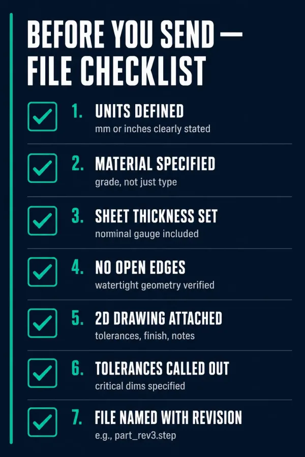
A clean checklist-style infographic listing the key items engineers should verify before sending CAD files to a manufacturer for quoting, including units, material, thickness, tolerances, and file naming.
Before you send files to a manufacturer, run through this checklist. Each item addresses a common source of delays, miscommunication, or rejected quotes.
- Sheet thickness is defined in the model or drawing. A zero-thickness surface model cannot be quoted for sheet metal—the manufacturer needs to know the raw material gauge.
- Units are correct and clearly stated. Do not assume the recipient uses the same unit system.
- No open edges or missing faces. A model with gaps in the surface geometry will fail import or require manual repair, adding days to the quoting process.
- A 2D drawing accompanies the 3D model. The drawing should specify material, tolerances, surface finish, and any secondary operations.
- Tolerances are explicitly called out for critical dimensions. If you do not specify tolerances, the manufacturer will apply their standard—which may or may not match your requirements.
- Surface treatment is specified (e.g., powder coat, anodize, zinc plate, or none). Leaving this blank means the manufacturer will quote raw, untreated parts.
- File names are clear and include a revision number. “bracket_final_v3.step” is better than “bracket.step” when multiple revisions are in circulation.
Zusammenfassung
- CAD files come in three types—native, exchange, and mesh. For sharing with manufacturers, STEP (3D) and DXF (2D) are the most reliable exchange formats.
- A 3D model is not a manufacturing specification. Always pair your model with a 2D drawing that specifies material, tolerances, and finish requirements.
- A few minutes of file preparation saves days of back-and-forth. Use the quoting checklist above to make sure your submission is complete before it reaches the manufacturer.