A eine einzelne fehlende Oberfläche in einer STEP-Datei kann Ihre Blechbestellung um zwei bis drei Tage verzögern. Der Hersteller öffnet die Datei, findet Geometrielücken in einem kritischen Biegebereich und sendet eine technische Klärungsanfrage an Sie zurück. Bis Sie neu exportieren und erneut senden, wurde Ihr gebuchter Produktionsslot an einen anderen Kunden vergeben. Dieses Szenario spielt sich täglich in der Auftragsfertigung ab — und es ist fast immer vermeidbar.
Was ist eine STEP-Datei?
Eine STEP-Datei ist ein herstellerneutrales 3D-CAD-Dateiformat nach ISO 10303, ein internationaler Standard, der in den 1980er Jahren entwickelt wurde, um ein hartnäckiges Problem in der Fertigung zu lösen: Kein einzelnes CAD-Programm konnte zuverlässig die nativen Dateien eines anderen Programms lesen. Das Akronym steht für Standard für den Austausch von Produktdaten.
Die in der alltäglichen Fertigung verwendete Dateikodierung ist definiert in ISO 10303-21 (auch STEP AP214 genannt). Wenn Sie eine Datei mit der Erweiterung .stp oder .step, sehen, betrachten Sie dasselbe Format — die beiden Erweiterungen sind austauschbar, und die Wahl hängt nur von der Software ab, die die Datei erstellt hat.
Im Gegensatz zu mesh-basierten Formaten wie STL speichert eine STEP-Datei parametrische Volumengeometrie unter Verwendung mathematischer Oberflächen (NURBS-Kurven und B-rep-Grenzflächendarstellungen). Das bedeutet, die Datei enthält die tatsächliche Form des Bauteils, nicht eine Annäherung aus Dreiecken.
Welche Daten enthält eine STEP-Datei tatsächlich?
Zu verstehen, was in einer STEP-Datei enthalten ist, erklärt, warum Hersteller darauf bestehen.
Eine STEP-Datei trägt das vollständige Volumenmodell eines Bauteils oder einer Baugruppe. Dies umfasst die präzise Geometrie jeder Fläche, Kante und jedes Eckpunkts, gespeichert als mathematische Oberflächendefinitionen statt als Polygonnetze. Das Ergebnis ist ein Modell, das gemessen, bearbeitet und geprüft werden kann — nicht nur visualisiert.
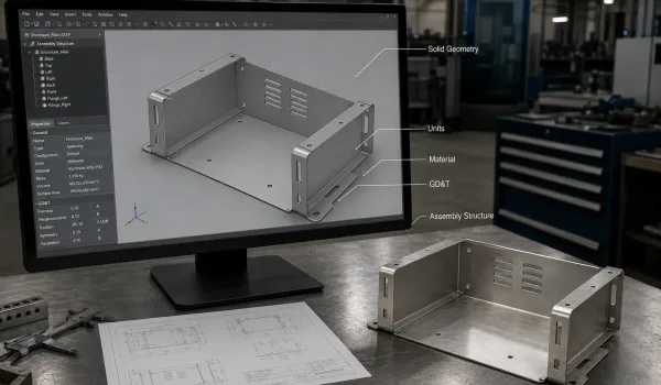
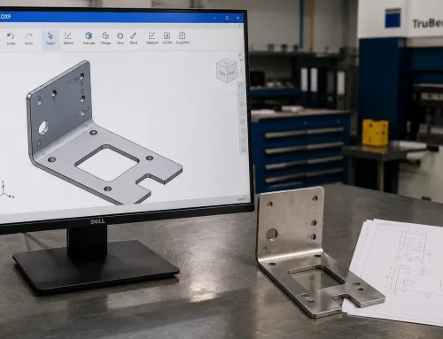
Ein STEP-Volumenmodell mit Hervorhebung der wichtigsten Konstruktionsdaten, die in der Datei enthalten sein können.
Über die Geometrie hinaus kann eine STEP-Datei einbetten:
- Maßeinheiten (Millimeter oder Zoll, übernommen aus dem Quell-CAD)
- Materialspezifikationen (wenn der Konstrukteur sie im Quellmodell zugewiesen hat)
- Geometrische Bemaßung und Tolerierung (GD&T) Daten — insbesondere in AP242, der neueren Revision
- Baugruppenstruktur und Bauteilbeziehungen für Mehrkomponenten-Dateien
Dies ist der entscheidende Unterschied zu STL, das nur ein trianguliertes Netz ohne technische Metadaten speichert. Ein Hersteller, der eine STEP-Datei erhält, kann Wandstärke extrahieren, Bohrungspositionen verifizieren und CNC-Werkzeugwege direkt generieren. Ein Hersteller, der eine STL-Datei erhält, kann nichts davon tun, ohne die Geometrie zuerst zu konvertieren oder zurückzuentwickeln — ein Schritt, der Fehler und Verzögerungen einführt.
Warum bevorzugen Hersteller STEP gegenüber STL und IGES?
Die Antwort läuft darauf hinaus, was der Hersteller mit Ihrer Datei tun muss, nachdem er sie erhalten hat.
STL-Dateien nähern die Oberfläche Ihres Bauteils mit Tausenden winziger Dreiecke an. Dies funktioniert für den 3D-Druck, bei dem der Drucker das Netz direkt liest. Aber für CNC-Bearbeitung oder kundenspezifische Blechfertigung, the manufacturer needs exact geometry — a triangle mesh cannot define a precise bend radius, a true cylindrical hole, or a flatness tolerance. When a shop receives an STL, they must either convert it (losing accuracy) or model it from scratch.
IGES files were the industry standard before STEP, and they do carry solid geometry. However, IGES has declining software support, inconsistent unit handling, and a tendency to convert splines into polygon approximations during export. Many modern CAD tools read IGES less reliably than STEP.
STEP files offer the widest software compatibility, the most complete data retention, and the least conversion risk. The table below summarizes the key differences:
| Dimension | SCHRITT | STL | IGES |
|---|---|---|---|
| Geometry type | Solid (NURBS / B-rep) | Mesh (triangles) | Solid (splines, often degraded) |
| Engineering data (GD&T, materials) | Ja | Nein | Eingeschränkt |
| Software compatibility | Universal | Broad but limited utility | Narrowing |
| Manufacturing readiness | Direct use | Requires conversion | Often requires cleanup |
| File size | Larger | Smaller | Mittel |
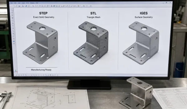
A visual comparison of STEP, STL, and IGES geometry showing why STEP is better suited to manufacturing.
For a sheet metal manufacturer, the practical implication is straightforward: STEP files can be loaded directly into nesting software, flat-pattern generation tools, and CNC programming environments. STL and IGES files cannot.
How to Prepare a STEP File for Manufacturing Submission
Sending a STEP file is not the final step — preparation matters. The following checklist addresses the issues that most commonly trigger technical clarifications or production errors.
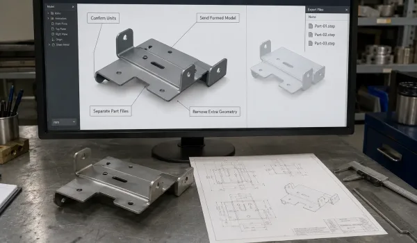
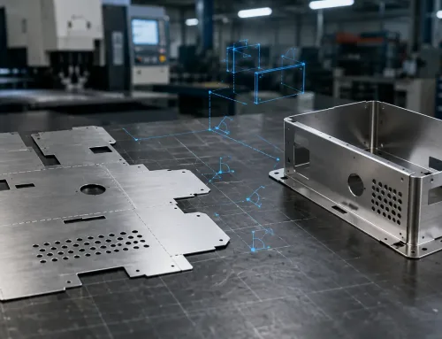
A manufacturing-ready STEP model showing the key checks for units, formed state, separate part files, and clean geometry.
Confirm the units. STEP files embed the unit system from the source CAD software. If your model was built in inches but the manufacturer’s system defaults to millimeters, every dimension will be off by a factor of 25.4. Verify the unit setting in your CAD program before export, or note the unit in your purchase order.
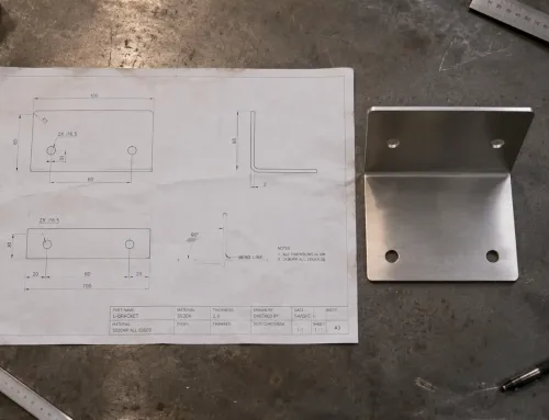
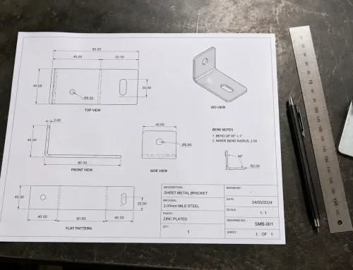
Check the part state for sheet metal. If you are ordering formed sheet metal parts, send the model in its formed (bent) state. Manufacturers generate their own flat patterns from the formed model using their bending equipment parameters. Sending a flat pattern instead of the formed model forces the shop to re-model the part — and their version may not match your design intent.
Send individual part files for separate quoting. If your assembly contains ten parts that will be manufactured separately, send ten individual STEP files rather than one assembly file. Assembly STEP files increase file size and require the manufacturer to extract and separate each component manually.
Remove non-manufacturing features. Before export, suppress or delete construction geometry, reference planes, internal sketches, and features that do not appear on the final part. These add file size and can confuse the manufacturer’s import process.
Use STEP AP214 unless your manufacturer confirms AP242 support. AP214 is the most widely supported revision. AP242 adds richer GD&T and PMI (product and manufacturing information) data, but not every shop’s software can read it. If your manufacturer has not specifically requested AP242, default to AP214.
Common STEP File Problems and How to Fix Them
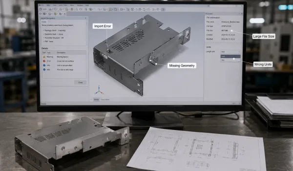
A STEP file inspection showing common problems such as missing geometry, incorrect units, import errors, and excessive file size.
The file will not open. Check the file extension — .stp, .step, .stpnc, und .p21 are all valid STEP encodings, but some viewers only recognize specific extensions. Try renaming the file. If the file was downloaded or transferred via email, it may have been truncated; re-export and re-transfer.
Geometry is missing or distorted after import. This usually indicates an export error from the source CAD. Re-export the part using the “export solid body” or “export as STEP AP214” option rather than a generic “save as.” Some CAD programs export only visible bodies by default — ensure all required bodies are visible before export.
The file is too large to transfer. Large assemblies produce large STEP files. Simplify the model by removing internal features, suppressing threads (which add enormous geometric complexity), and exporting only the components relevant to the current order. If file size remains a problem, ask your manufacturer whether they accept compressed STEP files (.stp.zip).
Dimensions are wrong after import. The most common cause is a unit mismatch between the file and the receiving software. Verify the units embedded in the STEP file header, and include the unit specification in your order documentation.
When You Do Not Need a STEP File
STEP is the manufacturing standard, but it is not always necessary.
Für 3D printing, STL is often sufficient — most slicing software reads mesh files directly, and the precision loss from triangulation is negligible at typical print layer heights.
Für visual rendering, marketing, or design review, lighter formats like OBJ, FBX, or 3D PDF load faster and are easier to share.
Für quick concept sharing within a team, native CAD files or lightweight visualization formats (JT, 3D PDF) are more practical.
The rule of thumb for choosing CAD file formats for manufacturing is simple: if the file is going to a manufacturer who will cut, bend, machine, or inspect your part, send STEP. If it is going to a colleague, a client, or a 3D printer, a lighter format may be the better choice.
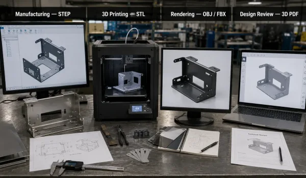
A practical comparison showing STEP for manufacturing and alternative file formats for 3D printing, rendering, and concept sharing.