A Eine DXF-Datei sieht wie eine vollständige Zeichnung aus. Sie enthält Geometrie, Layer und Koordinaten, die präzise genug erscheinen, um sie direkt an einen Fertigungsbetrieb zu senden. Aber eine DXF-Datei enthält keine Angaben zu Werkstofftyp, Blechdicke, Toleranz oder Biegeinformationen — die Daten, die eine Laserschneidmaschine oder Stanzmaschine tatsächlich benötigt, um Teile herzustellen.
Das Verständnis davon, was eine DXF-Datei enthält und was nicht,, kann Angebotsverzögerungen, Nacharbeit und Ausschuss verhindern.
Was eine DXF-Datei tatsächlich enthält
Eine DXF-Datei speichert 2D-Vektorgeometrie. Die Kernelemente sind Linien, Polylinien, Bögen, Kreise und Splines — die grundlegenden Bausteine jedes 2D-Profils. Diese Elemente beschreiben die Form einer Teilekontur im Koordinatenraum und verwenden X- und Y-Werte, um jeden Scheitelpunkt und jede Kurve zu definieren.
DXF-Dateien unterstützen auch Layer. Konstrukteure verwenden Layer, um verschiedene Geometrietypen zu trennen: Außenkonturen auf einem Layer, Innenausschnitte auf einem anderen und Biegelinien auf einem dritten. Layer helfen Fertigungsbetrieben zu verstehen, welche Geometrie geschnitten, welche geätzt und welche während der Produktion ignoriert werden soll.
Das Format speichert Daten als markierte Textpaare. Ein Gruppencode identifiziert den Datentyp, und ein Gruppenwert liefert den tatsächlichen Inhalt. In ASCII-DXF-Dateien — der häufigsten Variante — ist dieser Text menschenlesbar und kann in jedem einfachen Texteditor eingesehen werden. Diese Einfachheit ist ein Grund dafür, dass DXF seit über vier Jahrzehnten ein universelles Austauschformat geblieben ist.
Blöcke sind ein weiteres erwähnenswertes Merkmal. Ein Block ist eine wiederverwendbare Geometriegruppe — ein wiederkehrendes Lochmuster, ein Firmenlogo oder eine Standardvorrichtungsform. Blöcke reduzieren die Dateigröße und erleichtern Änderungen, aber sie können auch Importprobleme verursachen, wenn die empfangende CAM-Software sie anders interpretiert als das ursprüngliche CAD-System.
Was DXF nicht enthält
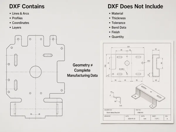
DXF-Dateien enthalten 2D-Geometrie und Layer, während Werkstoff, Dicke, Toleranzen, Biegungen, Oberfläche und Stückzahl separat angegeben werden müssen.
Dies ist der Teil, den die meisten Ingenieure übersehen, und er ist wichtiger als die Geometrie selbst.
Eine DXF-Datei spezifiziert nicht:
- Werkstofftyp — Stahl, Aluminium, Edelstahl, Kupfer oder eine andere Legierung
- Blechdicke — die Stärke oder Millimeterabmessung des Rohmaterials
- Toleranzen — zulässige Maßabweichung für kritische Merkmale
- Biegeradius oder Biegewinkel — Umformparameter für Gesenkbiegepressen-Operationen
- Anforderungen an die Oberflächenbeschaffenheit — Ra-Werte, Beschichtungen oder Nachbearbeitung
- Walzrichtung — wichtig für Sichtteile aus Edelstahl und Aluminium
- Stückzahl oder Losgröße — wie viele Teile der Auftrag erfordert
Wenn Sie eine DXF-Datei an einen Fertigungsbetrieb senden, senden Sie nur Geometrie. Alles andere — Werkstoff, Dicke, Toleranz, Oberfläche — muss aus einer separaten Zeichnung, einem Spezifikationsblatt oder einer Bestellung stammen.
Wenn der Fertigungsbetrieb eine DXF-Datei ohne diese Details erhält, muss er vor der Angebotserstellung um Klärung bitten. Dieser Rückfrageprozess verlängert die Durchlaufzeit um Tage.
Warum Fertigungsbetriebe DXF-Dateien anfordern
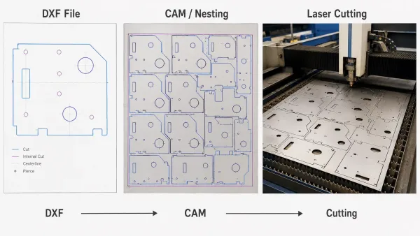
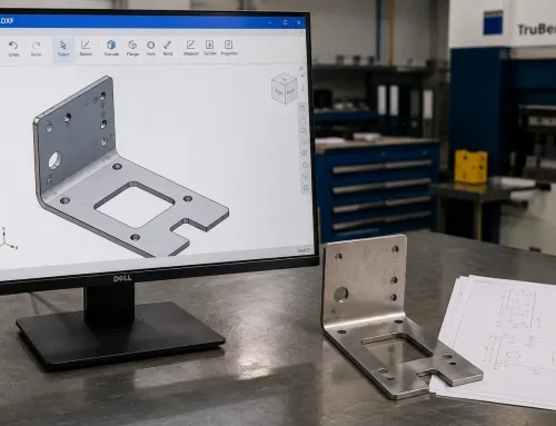
DXF-Geometrie kann in CAM-Software importiert werden, um Werkzeugwege für das Laserschneiden und die CNC-Blechbearbeitung zu generieren.
Für Laserzuschnitt-Dienstleistungen, Wasserstrahlschneiden und CNC-Stanzen verwenden Maschinen 2D-Profilgeometrie zur Generierung von Werkzeugwegen. DXF is the most widely supported format for this purpose because nearly every CAD system can export it, and nearly every CAM system — the software that controls cutting machines — can import it.
The format’s simplicity is its strength. A DXF file contains exactly the geometry the machine needs to trace a cutting path: coordinates, curves, and layer assignments. No embedded design history, no parametric constraints, no proprietary metadata that might confuse the receiving software.
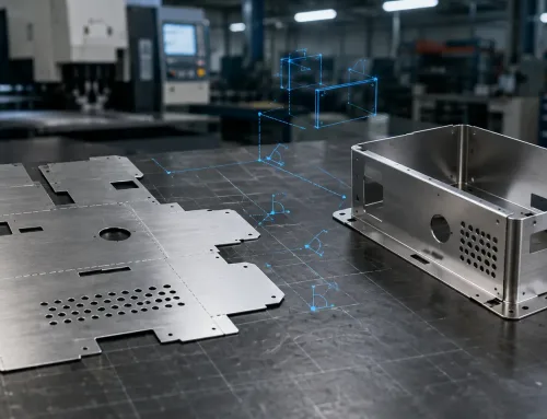
This makes DXF reliable for direct import into nesting software, which arranges multiple parts on a single sheet to minimize material waste.
For flat parts — brackets, plates, gaskets, flanges — DXF paired with a clear material callout on the purchase order is often sufficient. The fabricator reads the geometry, matches it to the specified material and thickness, and moves directly into production planning.
When DXF Is Not Enough
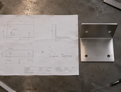
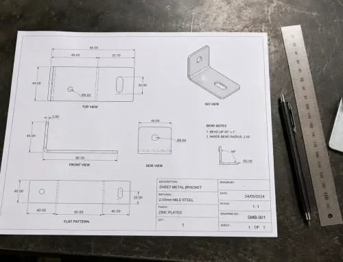
For parts with bends, weldments, or tight tolerances, DXF alone is not enough. A 2D DXF file cannot describe a 3D formed part. It cannot communicate bend sequence, tooling selection, forming direction, or the relationship between flat pattern and finished geometry.
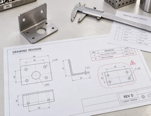
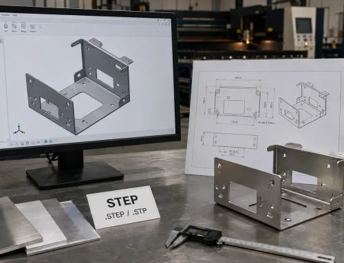
In these cases, fabricators prefer a combination: DXF for the flat pattern, and a 2D engineering drawing for sheet metal fabrication that defines bend details, material specifications, and critical dimensions. Some fabricators also accept STEP files for complex 3D geometry, which carry more information than a 2D drawing can represent.
DXF vs. DWG vs. STEP — Welches Dateiformat gesendet werden sollte
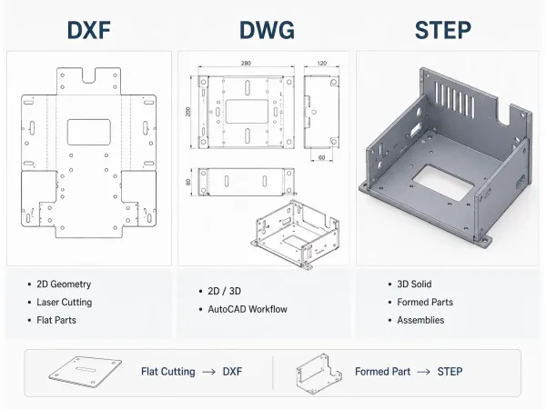
DXF is suited to 2D cutting, DWG to AutoCAD design workflows, and STEP to formed or complex 3D sheet metal parts.
Choosing the right CAD file format for manufacturing depends on what you are making and what your fabricator’s equipment can read. The table below compares the three most common formats in sheet metal fabrication.
| Feature | DXF | DWG | SCHRITT |
|---|---|---|---|
| Format type | Open exchange format | Proprietary (Autodesk) | ISO standard (ISO 10303) |
| Geometrie | 2D vector (limited 3D mesh) | 2D and 3D | Full 3D parametric |
| Am besten für | 2D cutting, profiling, flat patterns | Design and editing within AutoCAD | 3D model exchange, formed parts |
| Software support | Nearly universal across CAD/CAM | Mainly Autodesk ecosystem | Broad CAD support |
| Open format | Yes, documented by Autodesk | No, requires license | Yes, ISO standard |
For laser cutting and flat profiling, DXF is the standard choice. It gives the fabricator the 2D geometry the cutting machine needs without unnecessary complexity.
For 3D parts that will be formed, machined, or assembled, a STEP file for manufacturing provides more complete information. It carries parametric surfaces, solid geometry, and assembly structure that a 2D DXF cannot represent.
DWG works when both parties use AutoCAD, but it is not ideal for cross-platform exchange. If your fabricator uses a different CAD or CAM system, DWG files may require conversion — and conversion sometimes introduces geometry errors.
When in doubt, ask your fabricator which format they prefer. Most sheet metal fabricators will accept DXF for flat cutting and STEP for formed parts.
Häufige DXF-Exportprobleme, die zu Fertigungsverzögerungen führen
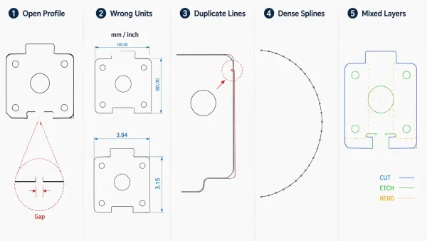
Open profiles, incorrect units, duplicate lines, dense splines, and mixed layers can create CAM import and cutting problems.
A DXF file that looks correct on screen can still cause problems on the shop floor. The issues below are the most common sources of delays, and each one traces back to how the file was exported rather than how the part was designed.
Open or unclosed profiles. When a part outline contains gaps between adjacent line segments, the cutting machine cannot recognize it as a closed contour. The CAM software may skip the geometry entirely, cut it incorrectly, or require manual repair by a technician. This delays the job because file repair happens before quoting or production — not during it.
Wrong scale or units. DXF files do not consistently specify measurement units. A file designed in millimeters may import as inches, producing parts 25.4 times too large or too small. This is one of the most common causes of rejected first articles, and it is entirely preventable by checking units before export.
Duplicate or overlapping lines. Merged design revisions sometimes leave stacked geometry — two or more lines occupying the same path. The machine may cut the same line twice, which doubles cycle time, increases the heat-affected zone on the material, and can cause edge quality problems on stainless steel and aluminum.
Excessive spline density. Curves exported from illustration software such as Adobe Illustrator or Inkscape often convert to dense polyline chains — hundreds of tiny line segments approximating a smooth curve. These generate oversized toolpaths that slow down cutting and may exceed the machine controller’s memory limits.
Layers not separated by function. When cut geometry, etch marks, and bend lines all sit on the same layer, the fabricator cannot distinguish them without a separate specification. This forces a manual review of every entity in the file, adding time and cost to the quotation process.
Why These Problems Increase Lead Time and Cost
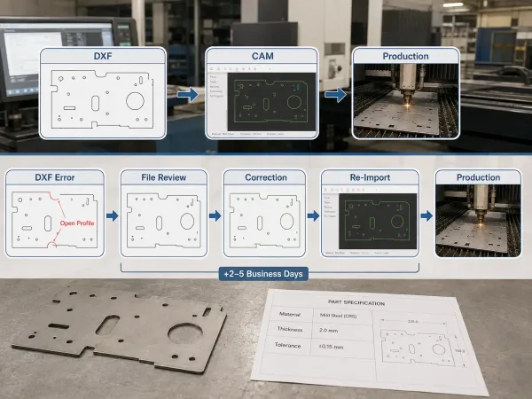
DXF file problems create extra review, correction, and CAM import steps before production can begin.
Each of the issues above creates a file review step that sits between your design release and the fabricator’s production planning. A technician must open the file, identify the problem, either fix it or request a correction, and re-import into the CAM system.
On a tight schedule, this added step can push delivery dates by two to five business days. On a complex job with multiple parts, the delay multiplies.
Checkliste vor dem Export — Was vor dem Senden einer DXF-Datei zu prüfen ist
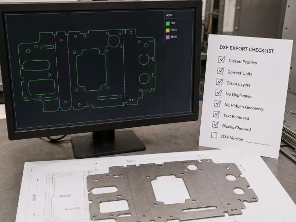
A pre-export DXF check helps prevent geometry, unit, layer, and compatibility problems before manufacturing.
Use this checklist before exporting a DXF for laser cutting or sheet metal fabrication. These checks take five minutes and can prevent days of delay.
- All part outlines are closed polylines with no gaps between segments
- Inner cutouts are separate closed profiles, distinct from the outer contour
- Units are consistent and match the intended measurement system (mm or inches)
- Layers are clearly named — for example: CUT for outer contours, ETCH for markings, BEND for bend lines
- No hidden, frozen, or construction geometry remains in the file
- No duplicate or overlapping lines exist on the same layer
- Text and annotations are removed or placed on a non-cut layer
- Block references are exploded if the receiving software has known import issues
- File is saved in a widely compatible DXF version — R2010 or earlier for maximum compatibility across CAM systems
When to Ask Your Fabricator Before You Export
Different fabricators use different CAM systems, and each system handles DXF import slightly differently. A two-minute conversation before export can prevent file revision cycles later.
Ask your fabricator:
- Which DXF version do your machines prefer?
- Do you want block references exploded or preserved?
- How should I name layers for cut, etch, and bend lines?
- Do you accept splines, or should I convert curves to polylines?
If you are preparing DXF files for laser cutting or sheet metal fabrication and want a second set of eyes on your export settings, our engineering team can review your files before they go to production. We work with DXF files daily and can flag common issues — open profiles, unit mismatches, layer problems — before they cause delays on the shop floor.