SDie Oberflächentextur bezeichnet die lokalen Abweichungen der Oberfläche eines gefertigten Bauteils von ihrer idealen geometrischen Form. Konstrukteure spezifizieren sie auf Zeichnungen, Hersteller kontrollieren sie während der Produktion, und Prüfer verifizieren sie vor dem Versand. Das Verständnis der Oberflächentextur hilft Ihnen, bessere Designentscheidungen zu treffen, unnötige Kosten zu vermeiden und sicherzustellen, dass Ihre Bauteile wie vorgesehen funktionieren.
Was ist Oberflächentextur?
Die Oberflächentextur sind die wiederkehrenden oder zufälligen Abweichungen von der Nennoberfläche eines Bauteils. Sie umfasst alle feinmaßstäblichen geometrischen Merkmale, die von Fertigungsprozessen hinterlassen werden—Schnittspuren eines Werkzeugs, Kornmuster vom Walzen oder Spitzen und Täler vom Schleifen.
In der Ingenieurpraxis ist die Oberflächentextur keine einzelne Zahl, sondern eine geschichtete Beschreibung davon, wie eine Oberfläche bei verschiedenen räumlichen Frequenzen von ihrer idealen Form abweicht.
Die Internationale Organisation für Normung definiert die Oberflächentextur in der ISO 21920-Reihe (die die früheren Normen ISO 4287 und ISO 1302 ersetzte). In der nordamerikanischen Praxis deckt, ASME B46.1 die Messung der Oberflächentextur ab und ASME Y14.36 deren Spezifikation in technischen Zeichnungen.
Oberflächentextur vs. Oberflächengüte: Was ist der Unterschied?
Die Begriffe “Oberflächentextur” und “Oberflächengüte” werden oft synonym verwendet, sind aber keine identischen Konzepte.
Oberflächentextur ist die geometrische Eigenschaft einer Oberfläche—was man mit einem Profilometer oder Mikroskop messen kann. Sie ist die objektive, quantifizierbare Beschreibung von Spitzen, Tälern, Rillenrichtung und Welligkeitsmustern.
Oberflächenbeschaffenheit (oder Oberflächenqualität) bezeichnet das Ergebnis eines auf eine Oberfläche angewendeten Fertigungsprozesses. Wenn ein Konstrukteur eine “Ra 0,8 μm Oberflächengüte” spezifiziert, beschreibt er das Zielergebnis. Wenn er von “Oberflächentextur” spricht, beschreibt er den messbaren physikalischen Zustand dieser Oberfläche.
In der Praxis kontrollieren Sie die Oberflächentextur durch Ihre Wahl des Fertigungsprozesses und der Parameter. Die gewünschte Oberflächengüte spezifizieren Sie auf der Zeichnung. Die beiden Konzepte überschneiden sich, aber Oberflächentextur ist der umfassendere und präzisere technische Begriff.
Die drei Komponenten der Oberflächentextur
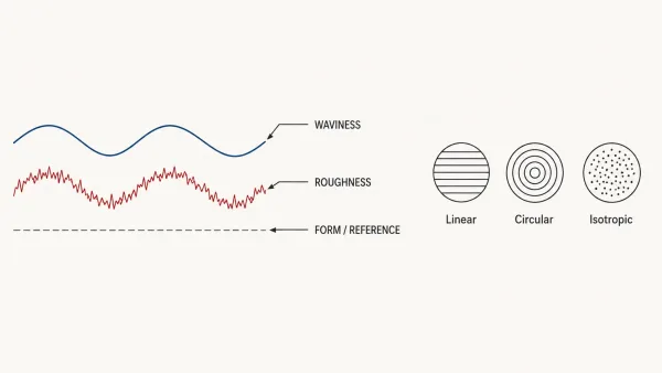
Ein Querschnittsprofildiagramm, das eine gefertigte Oberfläche in drei Komponenten unterteilt—Rauheit (feine Unregelmäßigkeiten), Welligkeit (längerwellige Undulationen) und Gesamtform—zusammen mit einer Draufsicht, die Rillenrichtungsmuster für lineare, kreisförmige und isotrope Oberflächen zeigt.
Die Oberflächentextur ist kein einzelnes Attribut. Sie setzt sich aus drei verschiedenen Komponenten zusammen, die jeweils Oberflächenabweichungen in einem anderen räumlichen Maßstab beschreiben.
Rauheit
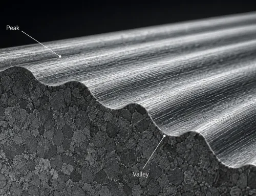
Rauheit ist die feinste und am engsten beabstandete Komponente der Oberflächentextur. Sie besteht aus den kleinen, unregelmäßigen Spitzen und Tälern, die vom Schneidwerkzeug, Schleifkorn oder Laserstrahl erzeugt wurden, der die Oberfläche geformt hat. Der Rauheitsabstand wird typischerweise in Bruchteilen eines Millimeters gemessen.
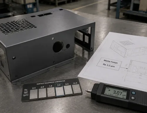
Rauheit ist die Komponente, die Konstrukteure am häufigsten auf Zeichnungen spezifizieren, üblicherweise als Ra-Wert (arithmetischer Mittenrauwert). Eine bearbeitete Oberfläche mit Ra 1,6 μm hat feinere, enger beabstandete Unregelmäßigkeiten als eine mit Ra 6,3 μm.
Welligkeit
Welligkeit ist die längerwellige Komponente der Oberflächentextur. Sie resultiert aus Faktoren wie Werkzeugmaschinenschwingungen, Werkstückdurchbiegung während des Schneidens oder Wärmeverformung beim Schweißen. Welligkeit hat einen größeren Abstand als Rauheit—typischerweise im Bereich von Millimetern bis zu Zehntelmillimetern.
Eine Oberfläche kann eine geringe Rauheit, aber eine hohe Welligkeit aufweisen. Zum Beispiel kann ein auf Ra 0,4 μm geschliffenes Bauteil noch sichtbare Welligkeit aufweisen, wenn die Schleifscheibe während des Durchgangs oszillierte. Welligkeit ist wichtig für Dichtflächen und Lageranwendungen, bei denen langwellige Abweichungen zu Leckagen oder ungleichmäßiger Lastverteilung führen können.
Rillenrichtung
Die Rillenrichtung ist die Richtung des dominierenden Oberflächenmusters. Sie spiegelt die Richtung des primären Bearbeitungs- oder Formgebungsvorgangs wider. Eine gedrehte zylindrische Oberfläche hat eine kreisförmige Rillenrichtung. Eine gefräste ebene Oberfläche hat eine lineare Rillenrichtung parallel zum Fräserweg. Eine kugelgestrahlte Oberfläche hat eine isotrope Rillenrichtung—keine dominierende Richtung.
Die Rillenrichtung beeinflusst, wie eine Oberfläche unter Gleitkontakt funktioniert, wie Beschichtungen haften und wie Licht von der Oberfläche reflektiert wird. Konstrukteure spezifizieren manchmal die Rillenrichtung auf Zeichnungen, wenn die Orientierung der Oberflächenspuren funktional wichtig ist—beispielsweise auf Dichtflächen, wo die Rillenrichtung senkrecht zur Richtung einer möglichen Leckage verlaufen sollte.
Wichtige Oberflächentextur-Parameter
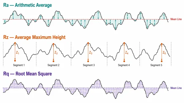
Eine einzelne Oberflächenprofillinie wird dreimal dargestellt, um zu veranschaulichen, wie Ra die durchschnittliche Abweichung misst, Rz die Spitzen-zu-Tal-Höhe über fünf Messlängen misst und Rq die quadratische Mittelabweichung misst—jeweils mit unterschiedlichen farbcodierten Anmerkungen hervorgehoben.
Mehrere Parameter quantifizieren die Oberflächentextur, aber drei erscheinen am häufigsten auf technischen Zeichnungen und in Qualitätsprüfberichten.
| Parameter | Name | Was es misst | Häufige Verwendung |
|---|---|---|---|
| Ra | Arithmetischer Mittenrauwert | Die durchschnittliche absolute Abweichung von der Mittellinie | Am weitesten verbreitet; universeller Rauheitsindikator |
| Rz | Gemittelte maximale Höhe | Die durchschnittliche Höhendifferenz zwischen den fünf höchsten Spitzen und fünf tiefsten Tälern über die Bezugslänge | Empfindlich gegenüber isolierten Spitzen und Tälern; verwendet für Lager- und Dichtflächen |
| Rq | Quadratische Mittelrauheit | Der quadratische Mittelwert der Abweichungen von der Mittellinie | Statistisch stabiler als Ra; verwendet in Forschung und vibrationsempfindlichen Anwendungen |
Ra ist die Standardwahl für die meisten Zeichnungen, da es gut verstanden, einfach zu messen und von allen wichtigen Normen unterstützt wird. Rz gives a better picture of extreme surface features that Ra might average out. Rq is mathematically more robust but less commonly specified in manufacturing practice.
A practical guideline: if your drawing currently specifies only Ra and you are seeing issues with isolated scratches or deep tool marks that pass inspection, consider adding an Rz requirement alongside the Ra specification.
Wie Fertigungsprozesse die Oberflächentextur beeinflussen
Jedes Blechverarbeitungsprozess leaves its own signature on the surface. Understanding this helps you choose the right process for your surface texture requirements—and avoid specifying finishes that are unnecessarily expensive or physically unachievable.
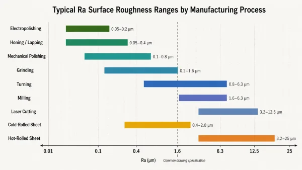
A horizontal bar chart displaying the achievable Ra roughness ranges for common manufacturing processes—including hot-rolled, laser cutting, milling, turning, grinding, polishing, and electropolishing—showing how each step progressively refines surface texture.
Raw material surfaces. Cold-rolled steel sheet typically arrives with Ra 0.8–1.6 μm. Hot-rolled steel is rougher, around Ra 3.2–12.5 μm. Stainless steel in 2B finish is approximately Ra 0.1–0.5 μm, while No. 4 (brushed) finish is around Ra 0.2–1.0 μm. The starting surface sets a baseline that subsequent operations can only modify, not fully erase.
Cutting processes. Laser cutting produces edge surfaces of approximately Ra 3.2–6.3 μm, with a thin heat-affected zone. Waterjet cutting leaves a slightly rougher edge (Ra 3.2–12.5 μm) with no thermal damage. Plasma cutting creates the roughest edges, typically Ra 12.5–25 μm. Shearing and punching produce clean-cut and fracture zones with different roughness levels on the same edge.
Forming and bending. Press brake bending can leave tool marks on the bend radius, especially with worn tooling. The inner radius typically shows compressive texture changes, while the outer radius may develop micro-cracking at tight bend ratios. Roll forming produces a more uniform surface but can introduce waviness from roller deflection.
Schweißen. MIG and TIG welding create weld beads with roughness that depends on operator skill, wire feed rate, and shielding gas. Laser welding produces a smoother, narrower weld with less heat-affected zone distortion. All welding processes can introduce oxidation discoloration on adjacent surfaces that affects both appearance and subsequent coating adhesion.
Blechveredelungsprozesse can further modify surface texture. Grinding can achieve Ra 0.2–0.8 μm. Mechanical polishing reaches Ra 0.05–0.4 μm. Electropolishing on stainless steel can produce Ra < 0.1 μm. Bead blasting creates an isotropic surface with Ra 0.8–3.2 μm, depending on media size and pressure.
Each post-processing step adds cost, so specifying the finest finish your part actually needs—not the finest one available—is good engineering practice.
Wie man Oberflächentextur in technischen Zeichnungen spezifiziert
Clearly defining Anforderungen an die Blechoberfläche on the drawing avoids ambiguity, reduces back-and-forth communication, and helps prevent parts from being made to the wrong standard.
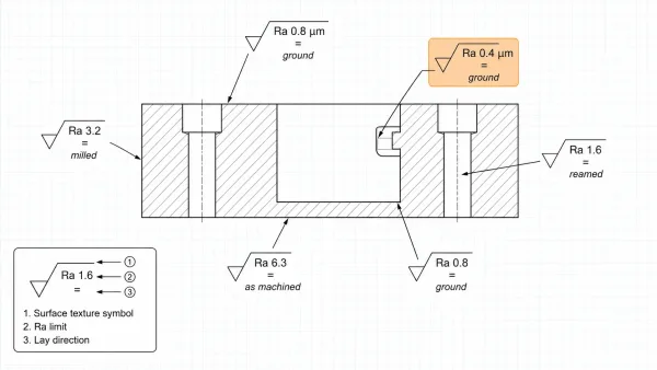
A portion of a simplified engineering drawing showing a machined part cross-section with ISO surface texture symbols placed on different surfaces, each annotated with Ra values, lay direction arrows, and processing method notes, demonstrating how surface requirements appear on an actual drawing.
Under ISO 1302 and the updated ISO 21920-1:2021, the basic surface texture symbol consists of two lines forming a V-shape with a horizontal line added at the vertex. The symbol is placed on the surface being specified, with the Ra value and any additional requirements written to the right of the symbol.
Common specification elements include:
- Ra value with unit (e.g., Ra 1.6 μm or Ra 63 μin)
- Sampling length (evaluation length) when it differs from the default
- Lay direction symbol (e.g., = for parallel, ⊥ for perpendicular, × for crossed)
- Processing method (e.g., “milled,” “ground,” “blasted”) when the method must be specified
- Surface texture limits with “max” or a tolerance band when the range matters
Two common specification errors that increase manufacturing cost unnecessarily:
- Specifying Ra 0.8 μm on all surfaces when only sealing or mating surfaces require it. Unnecessary precision on non-functional surfaces adds grinding or polishing cost with no performance benefit.
- Not specifying the evaluation length. A short evaluation length can give a misleadingly low Ra value. If your application is sensitive to waviness, specify a longer evaluation length or add a waviness parameter.
A practical recommendation: work with your manufacturer to determine which surfaces genuinely need controlled texture. On most sheet metal and machined parts, only 20–30% of surfaces are functionally critical. Specify those precisely and leave the rest as “as-machined” or “as-formed.”
Warum Oberflächentextur für die Bauteilleistung wichtig ist
Surface texture is not an abstract measurement—it directly affects how your parts perform in service.
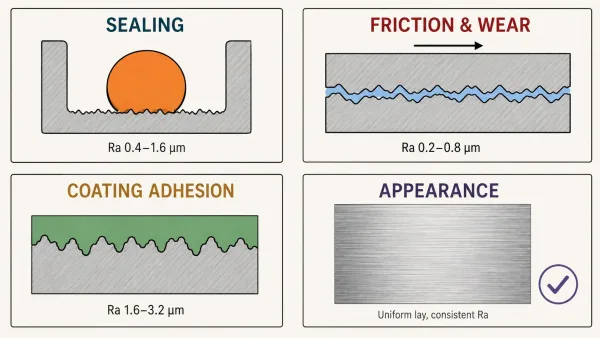
Four illustrated cross-section panels demonstrate how surface roughness influences sealing contact with an O-ring, sliding friction between two surfaces, mechanical adhesion of a coating layer, and visual uniformity of a brushed metal surface.
Sealing. Gasket and O-ring surfaces require controlled roughness to maintain a reliable seal. Too rough, and the seal cannot bridge the surface irregularities, leading to leakage. Too smooth, and O-rings may stick or experience excessive friction during assembly. For most elastomeric seals, Ra 0.4–1.6 μm is the practical range. For metal-to-metal seals, even finer control is needed.
Reibung und Verschleiß. Surfaces in sliding contact need a roughness level that balances low friction with adequate lubricant retention. A surface that is too smooth may experience adhesive wear (galling), while one that is too rough increases abrasive wear. Bearing surfaces typically specify Ra 0.2–0.8 μm depending on the bearing material and lubrication method.
Coating adhesion. Paint, powder coat, and plating adhere better to surfaces with slight roughness that provides mechanical “tooth.” A blasted or chemically etched surface with Ra 1.6–3.2 μm typically gives the best coating adhesion. Electropolished surfaces, while visually attractive, may require additional surface preparation before coating.
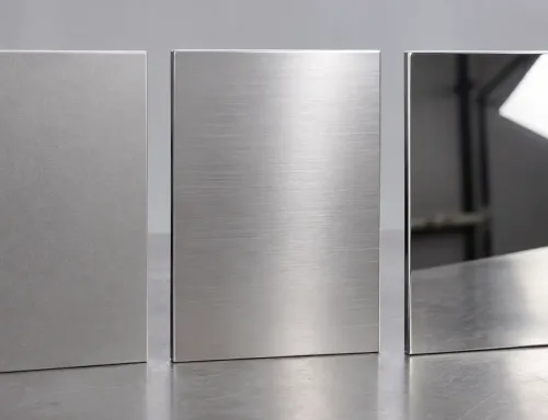
Appearance. Consumer-facing parts in electronics, medical devices, and architectural applications require consistent surface texture for visual quality. Brushed stainless steel (No. 4 finish) must show uniform, parallel lines without visible waviness or scratches. Surface texture consistency across multiple parts in an assembly is often more important than the absolute roughness value.
FAQs
This article is for informational purposes only. Surface texture requirements vary by application, material, and manufacturing process. Consult your manufacturer or a qualified surface metrology specialist to determine the appropriate specifications for your specific parts.