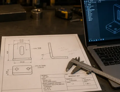
YSie haben eine umgeformte Blechhalterung konstruiert. Der Prototyp besteht die Prüfung, die Geometrie ist finalisiert, und nun benötigt die Fertigungszeichnung einen Wärmebehandlungshinweis.
Sie öffnen die Normen und stellen fest, dass es kein einzelnes Symbol gibt, das besagt “dieses Teil härter machen.” Der Hinweis muss ausgeschrieben werden — und er muss korrekt ausgeschrieben werden, denn vage oder unvollständige Wärmebehandlungshinweise sind einer der häufigsten Gründe, warum Zeichnungen zurückgeschickt werden, noch bevor die Produktion überhaupt beginnt.
Dieser Leitfaden erläutert genau, was in einen Wärmebehandlungshinweis auf einer Blechzeichnung gehört, wo er platziert wird, welche Verfahren für Blechteile gelten und wie man die Fehler vermeidet, die Nacharbeit verursachen.
Wo Wärmebehandlungshinweise auf einer Zeichnung hingehören
Wärmebehandlungsinformationen gehören nicht an eine einzelne feste Stelle. Wo Sie sie platzieren, hängt davon ab, wie die Informationen gelesen werden müssen — vom Fertiger, vom Wärmebehandler und vom Qualitätsprüfer.
Es gibt drei Standardplatzierungsoptionen:
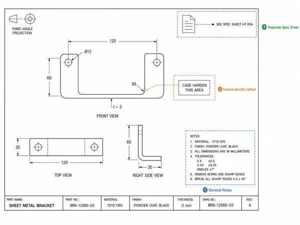
Eine saubere technische Illustration, die ein Engineering-Zeichnungslayout mit drei beschrifteten Bereichen zeigt — Allgemeine Hinweise, merkmalspezifischer Hinweis mit Bezugslinie und Verweis auf ein separates Spezifikationsblatt — die anzeigen, wo Wärmebehandlungsinformationen platziert werden.
Allgemeiner Hinweisblock. Dies ist die häufigste Stelle für prozessbezogene Wärmebehandlungsanforderungen, die für das gesamte Teil gelten. Auf einer technische Zeichnung, ein Hinweis wie “SPANNUNGSARMGLÜHEN NACH AMS 2759” im Schriftfeld oder Hinweisbereich teilt jedem nachgelagerten Leser mit, dass das Teil ein bestimmtes thermisches Verfahren erfordert.
Merkmalspezifischer Hinweis. Wenn die Wärmebehandlung für einen bestimmten Bereich gilt — zum Beispiel Einsatzhärten nur an den Zähnen eines Zahnrads oder der Verschleißfläche einer Halterung — bietet eine Bezugslinie oder ein Fähnchenhinweis an diesem Merkmal eine klarere Anweisung als ein allgemeiner Hinweis.
Separates Spezifikationsblatt. Bei Teilen mit komplexen oder mehrstufigen Wärmebehandlungssequenzen (Glühen, dann Härten, dann Anlassen) hält ein dediziertes Prozessspezifikationsblatt, das in den Zeichnungshinweisen referenziert wird, die Zeichnung sauber und die Anforderungen eindeutig.
Wenn Sie unsicher sind, welchen Ansatz Sie wählen sollen, gilt die allgemeine Regel: ein einfaches Verfahren kommt in die Hinweise; bereichsspezifische Behandlung erhält einen Merkmalshinweis; mehrstufige Sequenzen kommen auf ein separates Blatt.
Die fünf Elemente, die jeder Wärmebehandlungshinweis enthalten muss
Ein Wärmebehandlungshinweis ist keine einzelne Zeile. Er ist eine Reihe verknüpfter Informationen, und das Weglassen eines Elements schafft Raum für Fehlinterpretationen.
Hier sind die fünf Punkte, die erscheinen müssen — entweder direkt im Hinweis oder durch Verweis auf eine Norm.
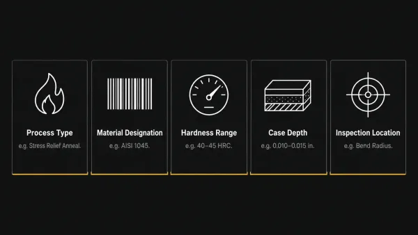
Eine horizontale Infografik mit fünf beschrifteten Abschnitten — Verfahrenstyp, Werkstoffbezeichnung, Härtebereich, Einsatzhärtungstiefe und Prüfstelle — jeweils als Symbol mit kurzem Beispieltext dargestellt, in einem sauberen Layout von links nach rechts angeordnet.
Element 1: Verfahrenstyp
Geben Sie das spezifische Wärmebehandlungsverfahren an.
Schreiben Sie nicht “wärmebehandeln” oder “härten” — diese Begriffe sind zu allgemein und zwingen den Wärmebehandler, Ihre Absicht zu erraten.
Gängige Verfahrensbezeichnungen umfassen Spannungsarmglühen, Weichglühen, Durchhärten, Einsatzhärten (Aufkohlen oder Carbonitrieren) und Ausscheidungshärten.
Jedes Verfahren erzeugt ein anderes Gefüge und mechanisches Ergebnis, daher muss die Zeichnung angeben, welches erforderlich ist.
Element 2: Werkstoffbezeichnung unter Verwendung von Normbezeichnungen
Der Blech-Werkstoffspezifikation auf der Zeichnung muss die korrekte Normbezeichnung verwenden — keinen Handelsnamen oder eine allgemeine Werkstoffbeschreibung.
Schreiben Sie “AISI 1045” statt “mittlerer Kohlenstoffstahl.”
Schreiben Sie “SAE 4140” statt “Chrom-Moly-Legierung.”
Wärmebehandler verlassen sich auf den exakten Legierungscode, um Ofentemperaturen, Haltezeiten und Abschreckmedien festzulegen. Eine falsche oder vage Werkstoffangabe kann dazu führen, dass eine gesamte Charge nach der falschen Spezifikation behandelt wird.
Element 3: Härtewert und -bereich
Geben Sie die Härte als Bereich an, nicht als Einzelwert.
Ein Hinweis von “40–45 HRC” ist realistisch und erreichbar; “42 HRC” ist es nicht, weil die Härte über ein Teil aufgrund von Unterschieden in der Querschnittsdicke, Randnähe und Materialschmelze variiert.
Geben Sie außerdem die korrekte Härteskala an.
Rockwell C (HRC) ist Standard für gehärtete Stähle; Rockwell B (HRB) für geglühte oder weiche Werkstoffe; Brinell (HB) für größere Komponenten.
Mixing scales without a conversion note is a frequent source of rejection — hardness conversions are approximate, and compounding approximations introduces error.
Element 4: Case Depth (When Applicable)
For case-hardened parts — those that are carburized or carbonitrided — the callout must distinguish between effective case depth (measured from the surface to a specific hardness level, typically 50 HRC) and total case depth (the full distance carbon has diffused into the part).
Specify which one you mean, and give a range.
Zum Beispiel:
“Effective case depth 0.007–0.012 in. at 50 HRC.”
A single case depth value, like a single hardness value, leaves too much room for interpretation.
Element 5: Inspection Location
The drawing must indicate where hardness testing should be performed.
Heat treatment alters the surface and core of a part differently, and hardness readings taken at the wrong location can falsely indicate that the process failed.
For a formed bracket, the critical inspection point might be the bend radius; for a wear surface, it might be the functional contact area.
Mark the inspection point on the drawing with a leader note or reference it in the general notes.
Gängige Wärmebehandlungsverfahren für Blech und wie man sie angibt
Sheet metal parts typically undergo a narrower range of heat treatment processes than heavy machined components. The following four are the most common.
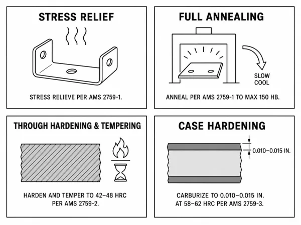
A four-panel grid showing simplified visual representations of stress relief annealing, full annealing, through hardening and tempering, and case hardening, each panel including the process name and a typical drawing callout example.
Stress relief annealing
This is the most frequently specified post-forming treatment for sheet metal.
Stress relief can reduce residual stresses introduced during Blechbiegen, stamping, or welding without significantly changing the material’s hardness or strength.
Typical callout:
“STRESS RELIEVE PER AMS 2759-1, METHOD X.”
Full annealing
Used when the part needs maximum ductility — for example, a component that will undergo further forming operations after the initial cut.
Full annealing heats the material above its upper critical temperature and slow-cools it.
Typical callout:
“ANNEAL PER AMS 2759-1 TO MAX 150 HB.”
Through hardening and tempering
For sheet metal parts that require high hardness across the full cross-section — springs, wear plates, cutting blades.
The callout must specify both the hardening and tempering steps, because tempering is what controls the final hardness.
Typical callout:
“HARDEN AND TEMPER TO 42–48 HRC PER AMS 2759-2.”
Case hardening (carburizing or carbonitriding)
Less common on thin sheet metal because the case-to-core ratio can be unfavorable on thin sections, but used on thicker sheet or plate components that need a hard surface with a tough core.
Typical callout:
“CARBURIZE TO EFFECTIVE CASE DEPTH 0.010–0.015 IN. AT 58–62 HRC PER AMS 2759-3.”
Blechspezifische Aspekte: Verzug, Toleranzen und Wärmebehandlung nach dem Umformen
Heat treatment on sheet metal is not the same as heat treatment on a 50 mm steel block.
Thin sections heat and cool quickly, warp more easily, and respond differently to quenching.
These factors directly affect what you write on the drawing.
Distortion is the primary risk.
A flat sheet metal part that is through-hardened will almost certainly distort. The thinner the part, the greater the distortion.
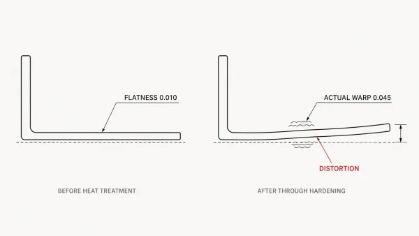
A technical illustration showing a flat sheet metal bracket on the left in its pre-heat-treatment state with flatness tolerance noted, and on the right the same bracket after through hardening with visible warpage and a callout indicating the distortion measurement.
If the application requires tight flatness tolerances after heat treatment, the drawing must call out the flatness requirement as a post-heat-treatment measurement — not just as a forming tolerance.
Otherwise, the part may pass forming inspection but fail after hardening.
Stress relief after forming reduces downstream problems.
Specifying stress relief annealing before any final machining or critical dimension verification is a standard practice for formed sheet metal parts.
On the drawing, place the stress relief note before the final tolerance callout in the process sequence so the fabricator knows the order of operations.
Dimensional compensation may be needed.
Heat treatment can cause predictable dimensional changes, including small amounts of growth or shrinkage, depending on the process and the specific Blechwerkstoffe being treated.
For precision assemblies, the Blechkonstruktion should define critical final dimensions as post-heat-treatment requirements and account for any predictable thermal movement during forming and processing.
This is uncommon on simple sheet metal brackets but critical on parts that interface with mating components.
Häufige Fehler, die Nacharbeit verursachen — und wie man sie vermeidet
The most expensive heat treatment problems are not caused by the heat treater. They are caused by unclear drawings.
Here are the five mistakes fabricators see most often.
Writing “heat treat to spec” without specifying which spec.
There are dozens of heat treatment standards, and each one covers different processes, materials, and acceptance criteria.
“Heat treat per spec” means nothing unless the spec number is named.
Specifying a single hardness value instead of a range.
Hardness is not uniform across a part.
A single value like “45 HRC” is either unachievable in some areas or too loose in others.
Always specify a range that accounts for the part’s geometry and material.

A split comparison showing two engineering drawing callouts side by side — the left side labeled “Incorrect” shows a single hardness value “45 HRC,” and the right side labeled “Correct” shows a hardness range “42–48 HRC,” with a brief annotation explaining why a range is required.
Using trade names instead of standard designations.
“Stainless 304” is acceptable in conversation but not on a production drawing.
The correct callout is “ASTM A240 Type 304” or the equivalent standard for your region and application.
Trade names can refer to different compositions across suppliers.
Omitting inspection locations.
If the drawing does not say where to test hardness, the heat treater will test wherever is convenient — which may not be the critical functional area.
This leads to parts that pass hardness testing but fail in service.
Mixing hardness scales without explanation.
If the drawing specifies “40 HRC” in one note and “380 HB” in another, the reader has to convert — and hardness conversions are approximate.
Specify one scale throughout, or if multiple scales are unavoidable, note the conversion basis (e.g., “per ASTM E140”).
Schnelle Checkliste vor dem Versenden der Zeichnung
Before releasing a production drawing with a heat treatment callout, verify these items:
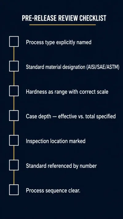
A clean checklist-style infographic showing seven review items that should be verified before releasing a drawing with a heat treatment callout, each item accompanied by a simple checkmark or checkbox graphic.
- Process type is explicitly named (not “heat treat” or “harden”)
- Material uses a standard designation (AISI, SAE, ASTM — not a trade name)
- Hardness is specified as a range with the correct scale (HRC, HRB, or HB)
- Case depth specifies effective vs. total and includes a range (if applicable)
- Inspection location is marked on the drawing
- The applicable standard is referenced by number (AMS 2759, SAE J411, etc.)
- Process sequence is clear if multiple treatments are required
Five minutes of review at the drawing stage can save five days of back-and-forth between engineering and the shop floor.