A Eine einzelne ungeschirmte Naht kann die Schirmdämpfung Ihres Gehäuses um 20 dB oder mehr reduzieren. Das ist der Unterschied zwischen Bestehen und Nichtbestehen eines EMV-Konformitätstests—und es kommt oft auf Entscheidungen an, die auf der Zeichnung getroffen werden, nicht in der Werkstatt.
Elektromagnetische Interferenz (EMI)-Abschirmung in Blechgehäusen ist keine Frage der Auswahl des richtigen Materials und damit erledigt. Die Abschirmleistung eines fertigen Gehäuses hängt von einer Kette von Designentscheidungen ab: wie Nähte verbunden werden, wo Erdungspunkte platziert werden, wie Lüftungsöffnungen dimensioniert werden und welche Oberflächenbehandlung die Kontaktzonen abdeckt. Jede dieser Entscheidungen beeinflusst gleichzeitig Schirmdämpfung, Fertigbarkeit, Kosten und Durchlaufzeit. Ingenieure, die diese früh in der Designphase berücksichtigen, vermeiden kostspielige Nacharbeit nach EMV-Tests.
Dieser Leitfaden behandelt die fünf Design-Dimensionen, die bestimmen, ob ein Blechgehäuse wie vorgesehen abschirmt.
Warum Blechgehäuse EMV-Tests bestehen, bevor das Produkt ausgeliefert wird
Die meisten EMI-Abschirmungsfehler werden nicht durch das falsche Material verursacht. Sie werden durch Spalten verursacht.
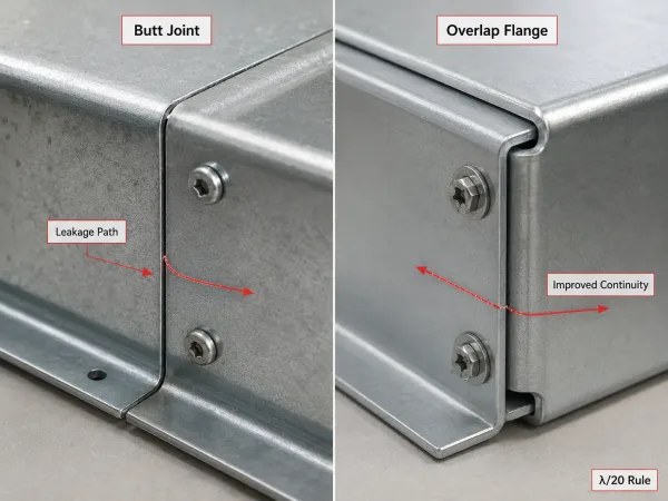
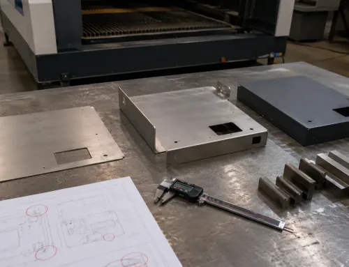
Kleine Spalten entlang von Gehäusenähten können bei hohen Frequenzen zu erheblichen EMI-Leckpfaden werden.
Jeder Schlitz, dessen längste Dimension sich einem Zwanzigstel der Wellenlänge (die λ/20-Regel) nähert wird zu einer effizienten Antenne. Bei 1 GHz liegt diese Schwelle bei etwa 15 mm. Eine Stumpfnaht mit einem 0,5 mm Spalt entlang einer 300 mm Naht kann die Abschirmung um 15–25 dB verschlechtern im Vergleich zu einem überlappenden Flanschdesign. In Mehrtafelgehäusen ist, jede verschraubte Verbindung, jeder abnehmbare Deckel und jede Kabeleinführung ein potenzieller Leckpfad. Die Schirmdämpfung auf einem Materialdatenblatt bedeutet wenig, sobald Fertigungstoleranzen, Beschichtungsdicken und Montagespalte berücksichtigt werden.
Materialauswahl: Wie sie Abschirmung, Fertigbarkeit und Kosten beeinflusst
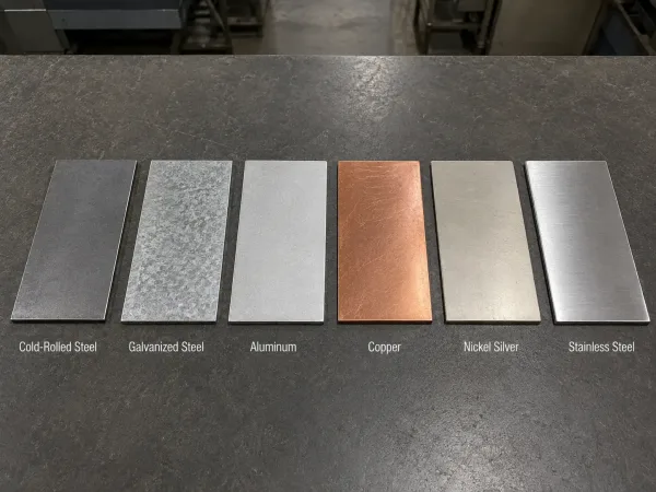
Gängige EMI-Gehäusematerialien unterscheiden sich in Abschirmleistung, Fertigungsverhalten, Gewicht und Kosten.
Die Materialwahl für ein EMI-Abschirmgehäuse umfasst drei miteinander verbundene Faktoren: elektrische und magnetische Eigenschaften, mechanisches Verhalten während der Fertigung und Gesamtkosten einschließlich Veredelung. Die folgende Tabelle fasst die gängigsten Blechmetalle für EMI-Abschirmgehäuse zusammen.
| Material | Abschirmstärke | Wichtige Fertigungshinweise | Typischer Anwendungsfall |
|---|---|---|---|
| Kaltgewalzter Stahl (CRS) | Ausgezeichnet, besonders unter 10 MHz | Starke magnetische Permeabilität absorbiert Niederfrequenzfelder; benötigt Pulverbeschichtung oder Plattierung für Korrosionsschutz | Industrieschränke, Telekom-Racks |
| Verzinkter Stahl | Ausgezeichnet | Zinkbeschichtung bietet Korrosionsschutz und erhält die Oberflächenleitfähigkeit | Außengehäuse, raue Umgebungen |
| Aluminium (5052 / 6061) | Gut über 10 MHz | Leichtgewichtig, leicht zu formen; benötigt dickere Stärke für äquivalente Steifigkeit; Eloxieren ist isolierend | Luft- und Raumfahrt, tragbare Geräte, Unterhaltungselektronik |
| Kupfer | Hervorragend | Höchste Leitfähigkeit; teuer, schwer und schwieriger zu formen | Medizinische Geräte, HF-empfindliche Instrumente |
| Neusilber (Kupfer-Nickel-Zink) | Very good | Good solderability and corrosion resistance; moderate cost | Board-level shields, precision enclosures |
| Stainless steel (304/316) | Mäßig | Corrosion-resistant; harder to form, requires more conservative bend radii | Medical, food processing, marine |
The manufacturing implications are often underestimated. Aluminum bends easily but has one-third the stiffness of steel, requiring thicker gauges for equivalent rigidity. Steel shields well at lower cost but introduces more springback during bending. Copper offers the best conductivity but is difficult to weld without distortion.
For most custom projects, cold-rolled carbon steel or galvanized steel offers the best balance of shielding, formability, and cost. Aluminum is right when weight matters, but plan for thicker walls and anodize exclusion zones at conductive contact surfaces.
Seam and Joint Design: Closing the Biggest Leakage Path
The seams where enclosure panels meet are the single largest source of EMI leakage in a sheet metal assembly. Closing them effectively requires deliberate design choices about joint geometry, welding method, and gasket specification.
Continuous Welding vs. Spot Welding
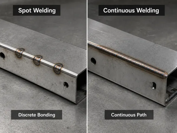
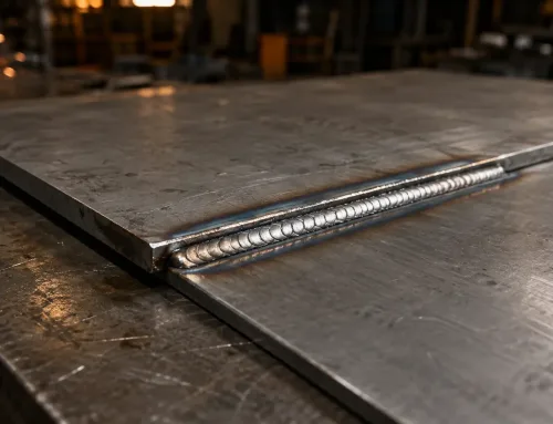
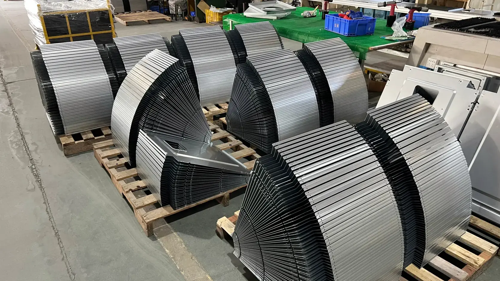
Continuous welding creates an uninterrupted conductive seam, while spot welding leaves gaps between bonding points.
Spot welding creates discrete bonding points with gaps between them. At frequencies above a few hundred MHz, those gaps behave as slot antennas. Continuous sheet metal welding—using laser, TIG, or seam welding—creates an unbroken conductive path. Continuously welded enclosures routinely outperform spot-welded equivalents by 10–20 dB above 300 MHz. The trade-off: continuous TIG welding on thin aluminum (below 1.5 mm) introduces more heat distortion. Laser welding offers continuous seams with minimal heat-affected zones, but at higher equipment cost.
Overlap Flanges vs. Butt Joints
In sheet metal lap joint design, an overlapping flange—where one panel extends over the adjacent panel by at least 5 mm—provides a much larger conductive contact area than a butt joint. It blocks field leakage and provides a gasket landing zone. Overlapping flanges add one extra bend per panel but eliminate the need for precision butt alignment during welding.
Gasket Grooves and Removable Panel Interfaces
Any removable panel—doors, access covers, service panels—requires a conductive gasket to maintain shielding continuity. The mating flanges must be flat within ±0.2 mm over the gasket landing zone for uniform compression. A recessed groove in the flange locates the gasket and controls compression depth. For low-volume projects, a flat flange with adhesive-backed conductive gasket is often sufficient.
Aperture Management: Ventilation Holes That Don’t Leak EMI
Every opening is a compromise between thermal management and shielding. The goal is to allow airflow while keeping apertures below the λ/20 threshold for the highest frequency of concern.
The λ/20 Rule and Vent Patterns
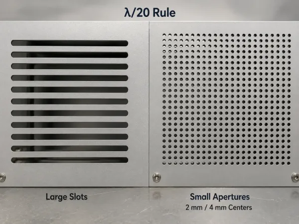
Smaller ventilation apertures help maintain airflow while reducing EMI leakage at higher frequencies.
Bei 1 GHz, openings should be smaller than 15 mm. Bei 6 GHz, the limit drops to about 2.5 mm. Replace a few large slots with many small holes: an array of 2 mm diameter holes on 4 mm centers provides roughly 25% open area for airflow while keeping each aperture well below the leakage threshold.
Honeycomb Vents, Perforated Sheets, and Mesh Panels
When higher airflow is required, three options are common:
- Honeycomb vents use thin-walled conductive cells that act as waveguides below cutoff, blocking high-frequency EMI while allowing airflow. They are the gold standard but add cost and assembly complexity.
- Perforated sheet metal is laser-cut with custom hole patterns. Cost-effective and integrated into the fabrication process, but hole size and spacing must be calculated against the target frequency.
- Mesh panels—stainless steel or copper mesh riveted behind a larger opening—offer high airflow at moderate cost. The mesh-to-frame bond must be conductive around the entire perimeter.
Complex perforation patterns increase laser cutting time and may require deburring. For high-volume projects, stamping can produce perforated panels at lower per-unit cost, but tooling investment is significant.
Grounding and Bonding: Making the Enclosure a Single Conductive Body
An enclosure is only as effective as its electrical continuity. Every panel, door, and cover must be bonded to a common ground at low impedance.
Grounding Point Design
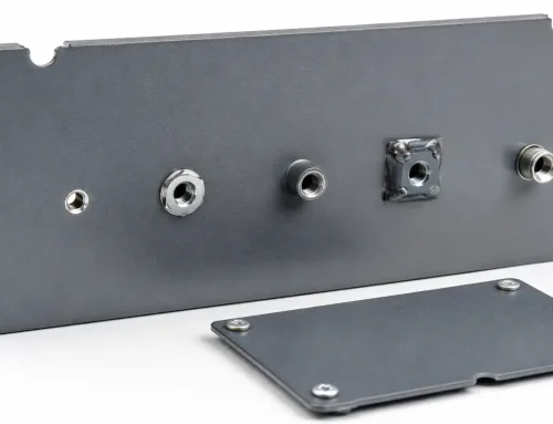
Each isolated panel should have at least one grounding point connected to the main chassis—welded studs, tapped holes with serrated washers, or bonding straps. Target contact resistance: below 2 milliohms. Place grounding points close to seam junctions and cable entry points, where leakage risk is highest. Do not rely on bolted joints alone; the contact area through a bolt head is small, and oxidation increases resistance over time.
Why Surface Finish at Contact Zones Matters
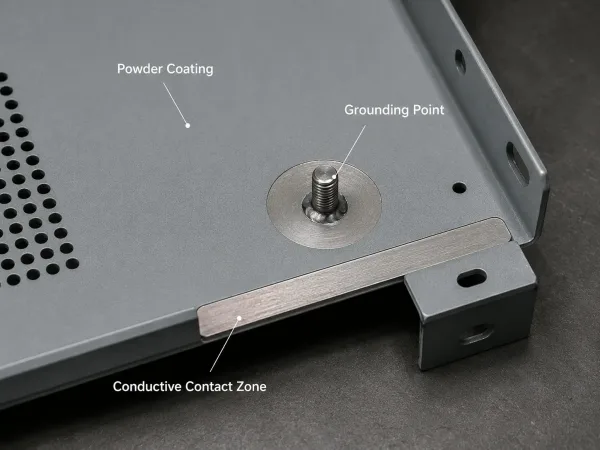
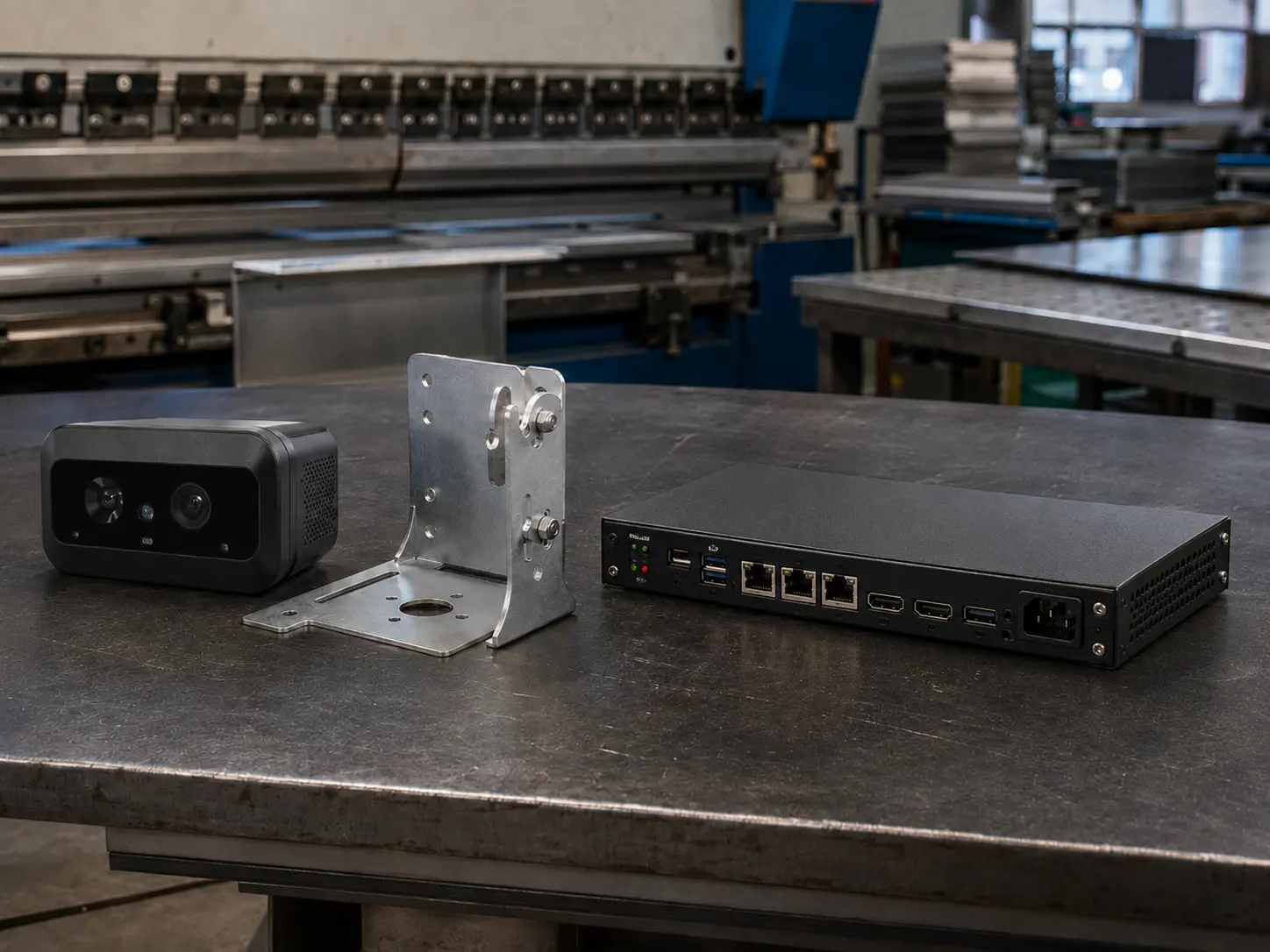
Grounding points and gasket contact zones must remain conductive when insulating surface finishes are applied.
In pulverbeschichteten Blechgehäusen, the coating provides an excellent corrosion barrier, but it is electrically insulating. If a gasket landing zone or grounding point is powder-coated, the conductive path is broken.
The solution is masking: specify which surfaces must remain bare metal or receive a conductive finish (chromate conversion, zinc plating). For aluminum enclosures, anodizing is also insulating—Type II adds 0.005–0.025 mm per side, Type III up to 0.05 mm. If anodizing is required, conductive contact zones must be masked before the process. This is one of the most common oversights in EMI enclosure design, and it is almost always caught after parts return from finishing with insulating coatings on the very surfaces that need to conduct.
Specifying EMI Shielding Requirements on Your Drawings
The design principles above are only effective if they are communicated clearly to the fabricator. A drawing that specifies material and dimensions but omits conductive contact zones, gasket specifications, and masking requirements will almost certainly result in a part that does not shield as intended.
What to Call Out on Your Drawings
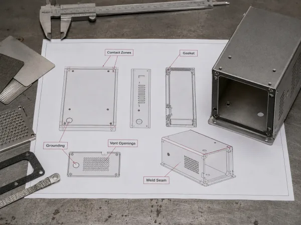
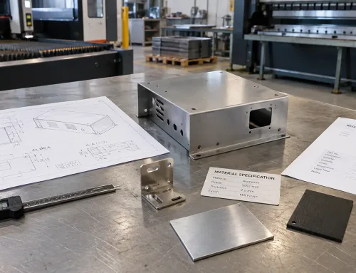
An EMI enclosure drawing should clearly define conductive zones, grounding points, gaskets, ventilation openings, and weld seams.
A complete EMI shielding drawing package should include:
- Material and thickness, with conductivity requirements if standard alloys are insufficient.
- Conductive contact zones: mark which surfaces must remain bare metal or receive a conductive finish. Use hatching, color coding, or a dedicated note.
- Gasket specification: type (conductive elastomer, fabric-over-foam, form-in-place), compression range, and groove dimensions with tolerances.
- Grounding points: location, type, and target contact resistance.
- Ventilation aperture requirements: maximum hole size or shielding effectiveness target.
- Welding requirements: continuous vs. spot, seam location, post-weld treatment.
- Applicable EMC standard or shielding effectiveness target over the required frequency range.
Low-Volume vs. Production
For prototypes and low-volume runs (under 500 units), enclosures are typically laser-cut, bent, and welded. The drawing package should focus on bend accuracy, weld seam continuity, and gasket tolerances achievable with these processes.
For production quantities, stamping and deep drawing become viable. Deep-drawn enclosures eliminate corner seams entirely, improving shielding by up to 10 dB. Tooling investment is substantial ($5,000–$30,000), but per-unit cost drops significantly. If you are unsure which path fits your volume and shielding requirements, a DFM review at the RFQ stage is the most efficient way to find out.