Yunser Blechteil besteht jede DFM-Prüfung — korrekter Biegeradius, Standardlochgrößen, ordnungsgemäße Materialstärke. Die Abwicklung verschachtelt sich effizient, die Toleranzen sind erreichbar, und das Angebot kommt ohne Warnsignale zurück.
Dann beginnt die Produktion, und der Montagetechniker meldet sich:
“Ich kann keinen Schlüssel an diese Schrauben ansetzen.”
Der Werkzeugzugang ist einer der am meisten übersehenen Aspekte der Blechkonstruktion. Er taucht selten in der automatisierten DFM-Analyse auf, weil Software die Geometrie prüft — Lochdurchmesser, Randabstände, Biegefreiräume — aber nicht simuliert, ob eine menschliche Hand mit einem echten Werkzeug ein Befestigungselement im Inneren eines umgeformten Gehäuses physisch erreichen kann.
Wenn das Problem in der Werkstatt auftritt, bedeutet die Behebung normalerweise, das Teil neu zu schneiden oder neu zu biegen.
Dieser Leitfaden erklärt, wie Blechteile konstruiert werden, die den Werkzeugfreiraum von Anfang an berücksichtigen, und behandelt die beteiligten Werkzeuge, die Befestigungsauswahl, die den Zugang beeinflusst, die Rolle der Montagereihenfolge und die Unterschiede zwischen Prototypen- und Serienumgebungen.
Warum der Werkzeugzugang bei der Blechkonstruktion übersehen wird
Die Ursache ist einfach: CAD-Umgebungen enthalten keine Werkzeugmodelle.
Wenn ein Konstrukteur eine Schraube in einer 3D-Baugruppe platziert, bestätigt die Software, dass die Schraube durch das Loch passt und der Kopf benachbarte Merkmale nicht berührt.
Was sie nicht prüft, ist, ob ein Steckschlüssel — der breiter als der Schraubenkopf ist und Platz zum Drehen benötigt — in denselben Raum passt.
Die Schraube ist geometrisch korrekt, aber praktisch unzugänglich.
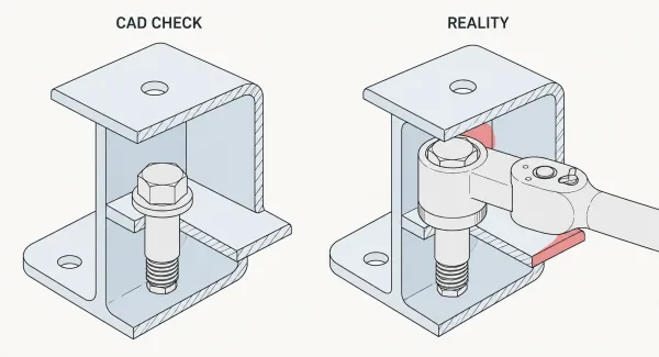
Eine technische Gegenüberstellung, die vergleicht, wie eine Schraube die CAD-Freiraumprüfungen besteht (links) gegenüber der Kollision eines Steckschlüssels mit der umgebenden Geometrie in der realen Baugruppe (rechts), wobei rote Zonen die Kollision hervorheben.
Diese Lücke besteht, weil die meisten DFM-Richtlinien für Blech sich auf die Fertigbarkeit konzentrieren — kann das Teil lasergeschnitten, gebogen und oberflächenbehandelt werden — statt auf die Montierbarkeit.
Der Design-Review-Prozess erkennt Probleme wie unmögliche Biegefolgen oder Merkmale zu nah an einer Kante, aber er fragt selten:
“Wie zieht der Techniker dieses Befestigungselement tatsächlich fest?”
Das Ergebnis ist ein Teil, das einfach zu fertigen und schwierig zu montieren ist.
Gängige Werkzeuge und der erforderliche Freiraum
Verschiedene Montagevorgänge erfordern verschiedene Werkzeuge, und jedes Werkzeug hat spezifische Platzanforderungen.
Die folgende Tabelle fasst die gängigsten Werkzeuge in der Blechmontage und den Mindestfreiraum, den sie zum Arbeiten benötigen, zusammen.
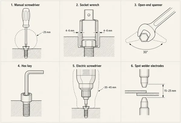
Ein Querschnittsdiagramm, das die Mindestfreiraumhüllen zeigt, die sechs gängige Montagewerkzeuge benötigen — Schraubendreher, Steckschlüssel, Maulschlüssel, Inbusschlüssel, Elektroschrauber und Punktschweißelektroden — mit beschrifteten Hauptmaßen.
| Werkzeug | Mindestfreiraumanforderung | Hinweise |
|---|---|---|
| Manueller Schraubendreher | Geradliniger Zugangspfad, ~25 mm Durchmesser | Benötigt Platz für Handgelenksdrehung |
| Steckschlüssel | Senkungsdurchmesser sollte 4–6 mm größer als der Schraubenkopf sein | Schlagschrauber benötigen noch mehr Platz |
| Maulschlüssel | Mindestens 30° Schwenkwinkel pro Hub | Bei 15° oder weniger kann das Festziehen einer Schraube über 10 Minuten dauern |
| Inbusschlüssel (Allen key) | Vertikaler Zugang über dem Befestigungselement | Funktioniert in engen seitlichen Räumen, in denen Maulschlüssel nicht schwenken können |
| Elektrischer/pneumatischer Schraubendreher | ~35–45 mm Durchmesser Freiraum | Größerer Körper als manueller Schraubendreher; benötigt einen geraderen Anfahrtswinkel |
| Punktschweißelektroden | Depends on electrode tip geometry, typically 15–25 mm access gap | Electrodes must reach both sides of the joint simultaneously |
| Adhesive applicator nozzle | ~10–15 mm access width | Must maintain consistent bead path; cramped space causes uneven application |
A common mistake is designing clearance only for the manual tool used during prototyping.
On a production line, the technician may use an electric screwdriver or pneumatic wrench that is significantly larger.
If the design does not account for this, the assembly works fine in small quantities but becomes a bottleneck at volume.
Befestigungszugang: Hardware an den verfügbaren Raum anpassen
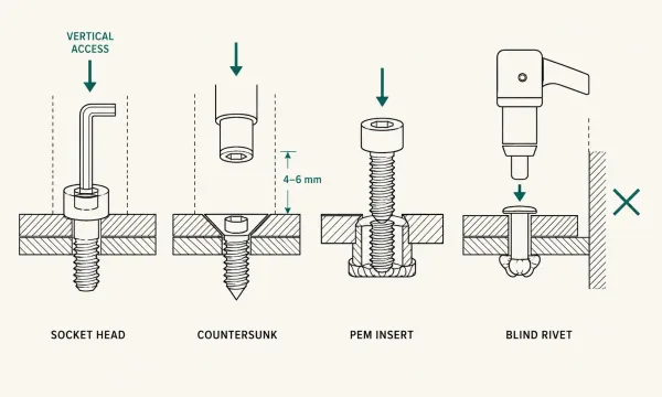
Cross-section comparison of four fastener types — socket head cap screw, countersunk screw, PEM insert, and blind rivet — showing the tool approach direction and access envelope for each.
The fastener you choose directly determines the tool access you need.
When space is constrained, changing the fastener is often simpler and cheaper than redesigning the surrounding geometry.
Socket Head Cap Screws
Socket head cap screws (driven with a hex key from above) are the most space-efficient option for tight assemblies.
The tool enters vertically, so there is no need for lateral swing clearance.
This makes them the default choice inside deep enclosures or between closely spaced walls.
Countersunk Fasteners
Countersunk fasteners sit flush with the surface and can reduce the overall clearance envelope, but they still need enough room above for the driving tool.
A countersunk screw driven by a socket wrench requires a counterbore that is at least 4–6 mm wider than the head diameter — the same rule applies regardless of the head style.
Self-Clinching PEM Inserts
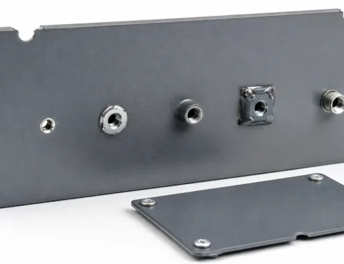
Self-clinching PEM inserts (such as PEM nuts and standoffs) are pressed into the sheet from one side, so the fastener itself does not require access from both sides.
However, the mating screw still needs tool access from the top.
If the insert is placed in a location that becomes inaccessible after other components are installed, the advantage is lost.
Rivets and Blind Fasteners
Rivets and blind fasteners can be set from one side only, which eliminates the need for rear access.
They are useful when the back side of the assembly is blocked by a wall, a mounting surface, or another component.
The tradeoff is that riveted joints are generally not removable for service.
The guiding principle is this: choose the fastener to fit the available access, not the other way around.
If you first select a bolt type and then try to find room for the wrench, you are working backward.
Montagereihenfolge und Planung der Werkzeugkanäle
A sheet metal assembly is not a single part — it is a sequence of operations performed in a specific order.
The order in which components are installed determines which tool channels remain open at each step.
Consider a typical electronics enclosure with a base tray, internal mounting brackets, a PCB, and a cover panel.
If the mounting brackets are fastened from inside the tray, the technician must attach all brackets before dropping in the PCB.
Once the PCB is in place, it blocks access to the bracket screws.
If the design assumes all fasteners are accessible at the end of assembly, the sequence breaks down.
The practical approach is to work backward from the final assembly state:
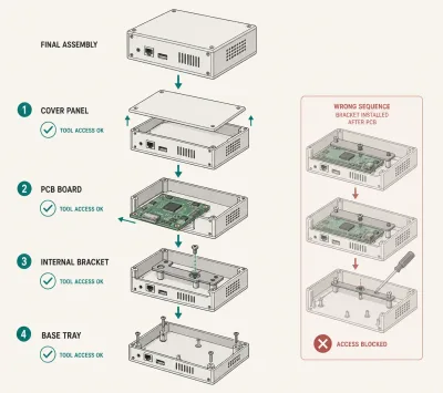
A reverse assembly sequence flowchart illustrating how to verify tool access by working backward from the final assembly state, component by component.
- Start with the last component installed (usually the cover or top panel). Identify its fasteners and confirm tool access exists with everything else already in place.
- Move to the second-to-last component. Confirm its fasteners are accessible with all subsequent components removed but all prior components installed.
- Continue backward through each layer until you reach the first operation.
This reverse-sequence check catches the most common failure mode:
A part that is easy to install individually but impossible to reach after the next component goes in.
In our experience reviewing customer drawings, roughly one in four enclosures has at least one fastener that becomes inaccessible once the assembly sequence is followed.
For multi-level assemblies with stacked internal components, every layer needs its own independent tool path.
A fastener buried under two layers of brackets and wiring is not accessible regardless of how large the opening above it is — the tool cannot navigate the obstacles.
Prototyp vs. Serie: Unterschiedliche Werkzeuge, unterschiedliche Freiräume
The gap between prototype and production tool requirements is a frequent source of surprises.
During the sheet metal prototyping stage, an engineer assembles a few units by hand using manual tools in an open benchtop environment.
The assembly feels straightforward.
Then the design moves to a production line, and the same assembly becomes a recurring problem.
The differences are significant:
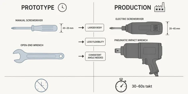
A side-by-side comparison showing the size and capability differences between manual tools used during prototyping and power tools used in production, with key dimensions labeled.
| Faktor | Prototype Stage | Production Stage |
|---|---|---|
| Tool type | Manual screwdriver, hand wrench | Electric/pneumatic screwdriver, power wrench |
| Tool size | Smaller, more maneuverable | Larger body, less flexibility |
| Assembly speed target | No time pressure | Takt time of 30–60 seconds per station |
| Technician skill | Engineer who knows the design | Operator following a work instruction |
| Access angle flexibility | Can tilt, rotate, work around obstacles | Needs consistent, repeatable approach angle |
An electric screwdriver used on a production line is typically 35–45 mm in diameter, compared to 20–25 mm for a manual driver.
A power wrench needs both space for its larger socket and clearance for its body.
If the design was validated only with hand tools, these production tools may not fit.
The solution is to include tool access in the mass-production readiness review from the start, even if the first units are assembled by hand.
It is always easier to use a smaller tool in a large space than to fit a larger tool into a space designed for a smaller one.
If production tooling is not yet finalized during the design phase, use conservative clearance estimates — err on the side of more space, not less.
Design-Checkliste: Überprüfung des Werkzeugzugangs vor der Zeichnungsfreigabe
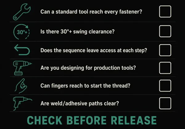
A six-point design checklist for reviewing tool access in sheet metal assemblies before releasing drawings for fabrication.
Before releasing a sheet metal drawing for fabrication, walk through each fastener and assembly operation with these questions:
- Can a standard tool reach every fastener? Place a simplified tool model in your CAD assembly and check for collisions with surrounding geometry.
- Is there enough swing clearance for wrenches? If a spanner cannot rotate at least 30° per stroke, consider switching to a socket head cap screw with vertical hex key access.
- Does the assembly sequence leave every fastener accessible at its installation step? Trace the sequence backward from the final state to confirm.
- Are you designing for production tools, not just hand tools? If the assembly will run on a production line, verify clearance with the actual power tool dimensions.
- Can a worker’s fingers reach the fastener location to start the thread? Deep recesses where fingers cannot align the bolt are a common source of dropped fasteners and cross-threading.
- Are weld or adhesive application paths clear of obstructions? If the assembly includes welding or adhesive bonding, confirm that the gun or applicator nozzle can follow a consistent path.
This checklist does not replace a full design review, but it catches the majority of tool access issues before they reach the shop floor.
FAQs
If you are designing a sheet metal assembly and want a manufacturing review of your tool access and fastener placement, upload your drawing to our team at SR-MFG.
*We will flag access issues before they become production problems.