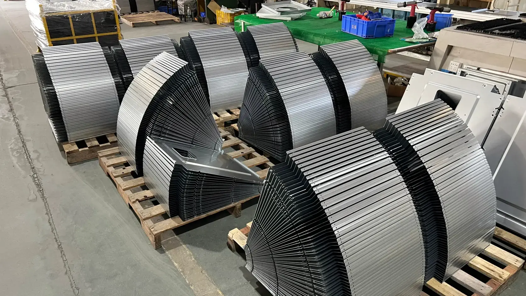
A Prozessfluss ist die Abfolge von Schritten, mit denen Rohmaterial in fertige Teile umgewandelt wird. In der Blechfertigungsprozess, deckt er jeden Vorgang ab, von der Designprüfung und Materialbeschaffung über Schneiden, Biegen, Schweißen, Oberflächenveredelung und Prüfung bis hin zur Lieferung, angeordnet in der Reihenfolge, in der sie tatsächlich stattfinden.
Jeder Schritt hat klare Eingaben, Ausgaben und Entscheidungspunkte. Für B2B-Teams, die Lieferanten bewerten, Angebote anfordern oder die Produktion verwalten, ist das Verständnis des Prozessflusses eines Blechherstellers eine der direktesten Möglichkeiten, seine Fertigungsfähigkeit, Kostenstruktur und Lieferzuverlässigkeit.
Was ist ein Prozessfluss?
Ein Prozessfluss beschreibt, welche Vorgänge ein Teil durchläuft, in welcher Reihenfolge und unter welchen Bedingungen. Eine einfache Möglichkeit, dies zu verstehen, ist das Modell:
Eingabe → Prozess → Ausgabe
Wenn Blech in ein Fabriksystem gelangt, durchläuft es eine Reihe von wertschöpfenden Vorgängen und verlässt es schließlich als fertige kundenspezifische Blechteile, bereit für die Montage oder den Versand.
Es ist wichtig, zwischen einem Prozessfluss und einem Prozessflussdiagramm. zu unterscheiden. Ein Prozessfluss ist die tatsächliche Abfolge von Vorgängen, die stattfindet. Ein Prozessflussdiagramm, oder PFD (Process Flow Diagram), ist ein visuelles oder schriftliches Dokument, das diese Abfolge darstellt.
Der Prozess existiert, ob er dokumentiert ist oder nicht. Jedoch kann er nur, wenn der Prozess aufgezeichnet wird, analysiert, verbessert und konsistent wiederholt werden.
Prozessfluss vs. Workflow vs. Flussdiagramm
Diese drei Begriffe werden in der Fertigung oft synonym verwendet, beziehen sich jedoch auf unterschiedliche Umfangsbereiche.
| Begriff | Umfang | Typische Verwendung |
|---|---|---|
| Prozessfluss | Die vollständige Fertigungssequenz für ein Teil oder eine Produktfamilie | Strategische Planung, Angebotserstellung, Lieferantenbewertung |
| Workflow | Aufgabenbezogene Bewegung, oft in digitaler Form — wer was tut, wann und in welchem System | Projektmanagement, ERP/MES-Konfiguration |
| Flussdiagramm | Eine visuelle Darstellung des Prozessflusses, oft verwendet für Analyse und Verbesserung | Lean-Aktivitäten, Ursachenanalyse |
In einer Fertigungsumgebung ist der Prozessfluss das Rückgrat. Workflows und Flussdiagramme sind unterstützende Werkzeuge, die darum herum aufgebaut sind.
Warum der Prozessfluss wichtig ist
Standardisierung und Wiederholbarkeit
Ein dokumentierter Prozessablauf stellt sicher, dass jede Schicht, jeder Bediener und jeder Produktionsstandort Teile nach demselben Standard fertigt. Ohne ihn existiert Fertigungswissen nur im individuellen Gedächtnis, was fragil, inkonsistent und für Kunden unsichtbar ist.
Funktionsübergreifende Abstimmung
Ein gemeinsamer Prozessablauf gibt den Teams aus Engineering, Produktion, Qualität und Einkauf einen gemeinsamen Referenzpunkt. Wenn ein Kunde fragt:, “Wie wird dieses Teil hergestellt?”, ist die Antwort klar und konsistent. Wenn eine technische Änderung vorgeschlagen wird, können ihre Auswirkungen auf nachgelagerte Vorgänge vor der Umsetzung bewertet werden.
Grundlage für kontinuierliche Verbesserung
Man kann nicht verbessern, was man nicht sieht. Ein dokumentierter Prozess macht Engpässe, redundante Schritte und Nacharbeitszyklen sichtbar. Er verwandelt abstrakte Ziele wie “Kosten senken” oder “Durchlaufzeit verkürzen” in konkrete, umsetzbare Verbesserungsprojekte. Dies ist der Ausgangspunkt für Lean Manufacturing und kontinuierliche Verbesserung.
Schlüsselelemente eines Prozessflusses
Prozessschritte und Reihenfolge
Jeder Prozessablauf besteht aus diskreten Schritten, die in einer bestimmten Reihenfolge angeordnet sind. Die Reihenfolge kann sein:
Linear — Schritt A, dann Schritt B, dann Schritt C
Parallel — Schritt A und Schritt B finden gleichzeitig statt, bevor zu Schritt C übergegangen wird
Bedingt — Wenn ein Teil bei Schritt B die Prüfung nicht besteht, durchläuft es die Nacharbeit und kehrt dann zu Schritt C zurück
Eingaben und Ausgaben in jeder Phase
Jeder Schritt verbraucht Eingaben wie ein Halbfertigteil, Rohmaterial, Energie oder Werkzeuge und erzeugt Ausgaben wie einen geschnittenen Rohling, ein gebogenes Bauteil oder eine geschweißte Baugruppe.
Die klare Definition dieser Input-Output-Beziehungen ist unerlässlich, wenn der Prozessablauf für Kostenschätzung und Produktionsplanung.
verwendet werden soll.
Entscheidungspunkte und Prüfstellen
Nicht jeder Schritt ist eine einfache Transformation. Ein Entscheidungspunkt, üblicherweise durch eine Raute in einem Flussdiagramm dargestellt, stellt eine Frage:
Liegt dieses Maß innerhalb der Toleranz?
Ist die Schweißnaht akzeptabel? Die Antwort bestimmt, ob das Teil weiterläuft, in die Nacharbeit geht oder verschrottet wird. Diese Prüfstellen zeigen genau, wo.
die Qualitätskontrolle in die Produktionslogik eingebettet ist
Standard-Symbole und Konventionen
- Die meisten Prozessflussdiagramme verwenden eine gemeinsame visuelle Sprache: Oval
- — Start- oder Endpunkt Rechteck
- — Prozessschritt oder Vorgang Raute
- — Entscheidungs- oder Prüfpunkt Pfeil
— Prozessrichtung.
Diese Symbole stammen aus weit verbreiteten Flussdiagramm-Konventionen, einschließlich gängiger Symbole für Start-/Endpunkte, Vorgänge, Entscheidungen und Flussrichtung. In der Praxis können Unternehmen sie basierend auf internen Dokumentationsstandards oder Kundenanforderungen anpassen.
Rollen und Verantwortlichkeiten Ein vollständiger Prozessablauf sollte identifizieren, wer für jeden Schritt verantwortlich ist. Das bedeutet nicht nur, welche Maschine den Vorgang ausführt, sondern auch welche Rolle, wie ein, Bediener, Prüfer oder Ingenieur.
, Entscheidungen trifft und das Ergebnis abzeichnet. Luft- und Raumfahrt sowie Medizintechnik, wo eine Rückverfolgbarkeit auf bestimmte Personen erforderlich sein kann.
Prozessfluss in der Blechfertigung: Schritt-für-Schritt-Übersicht
Das folgende Beispiel basiert auf dem Fertigungsprozessablauf für Blechumformung bei SR MFG. Die tatsächlichen Schritte können je nach Bauteilgeometrie, Werkstoff, Toleranzanforderungen, Auftragsvolumen und Kundenspezifikationen variieren.
Phase 1 — RFQ-Prüfung, DFM-Analyse und Angebotserstellung
Der Prozess beginnt, bevor Metall geschnitten wird. Nach Erhalt der technischen Zeichnung oder des 3D-Modells des Kunden, führt SR MFG eine Design-for-Manufacturability-(DFM)-Prüfung durch.
Zentrale Fragen sind:
- Kann der erforderliche Biegeradius erreicht werden?
- Sind die Toleranzen für den gewählten Werkstoff und das Verfahren angemessen?
- Kann das Bauteil effizient auf dem Blech verschachtelt werden?
DFM-Feedback in dieser Phase kann erhebliche Vorteile bei Kosten, Lieferzeit und Produktionsstabilität später im Prozess sichern oder freisetzen.
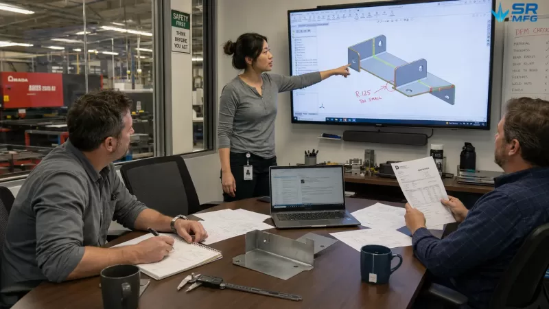
Eine DFM-Review-Sitzung vor der Angebotserstellung — Ingenieure bewerten Biegeradius, Toleranzen und Verschachtelungseffizienz an einem 3D-CAD-Modell, mit einem physischen Muster und einer kommentierten Zeichnung auf dem Schreibtisch
Phase 2 — Materialauswahl und Beschaffung
Basierend auf den technischen Spezifikationen wird das geeignete Blechmaterial ausgewählt, einschließlich Auswahl von Metallgüte und -dicke, Zustand oder Kondition sowie Oberflächenqualität.
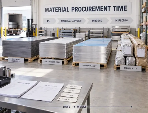
Die Materialverfügbarkeit beeinflusst direkt, wann die Produktion beginnen kann. Für Einkaufsteams ist dies eine häufige Ursache für Lieferzeitabweichungen, die sorgfältig überwacht werden muss.
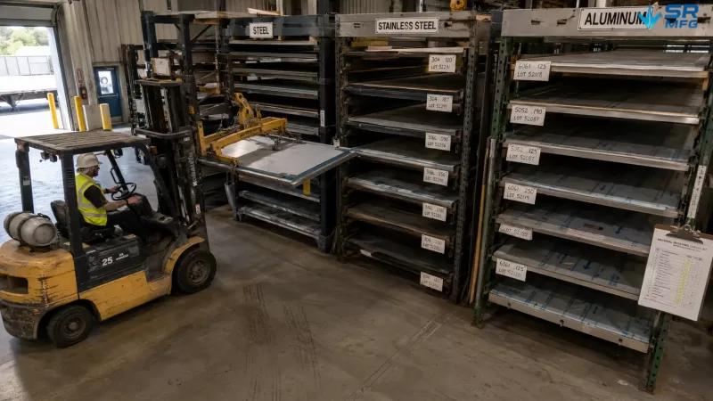
Lagerregale für Rohmaterial, organisiert nach Legierungsgüte und Blechdicke — Materialverfügbarkeit ist eine kritische Voraussetzung für den Start des Produktionsprozessablaufs
Phase 3 — Schneiden und Zuschnitt
Flaches Blech wird in das erforderliche Profil geschnitten. Die Methode hängt von der Geometriekomplexität, der Materialdicke, dem Produktionsvolumen und den Anforderungen an die Kantenqualität ab.
- Laserschneiden — Hohe Präzision, geeignet für komplexe Geometrien und dünnes bis mitteldickes Blech
- Stanzen / Revolverstanzen — Schnell und kosteneffizient für Standardmerkmale wie Löcher, Lamellen und Umformdetails bei Teilen mit hoher Stückzahl
- Scheren — Einfaches geradliniges Schneiden für grundlegende rechteckige Zuschnitte
- Wasserstrahlschneiden — Keine wärmebeeinflusste Zone, geeignet für dicke Platten oder wärmeempfindliche Werkstoffe
Verschachtelung, oder die effiziente Anordnung von Teilen auf einem Blech zur Maximierung der Materialausnutzung, ist eine wichtige Optimierungsmethode in dieser Phase.
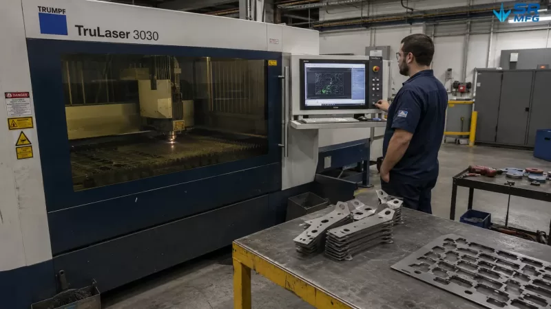
Eine Faserlaserschneidmaschine bearbeitet ein verschachteltes Blech mit Stahlhalterungen — der Bediener überwacht den Schneidfortschritt auf dem HMI-Bildschirm, während fertige Teile und Restgitter auf dem Ablagetisch anfallen
Phase 4 — Umformen und Biegen
Geschnittene Zuschnitte werden durch Blechbiegen auf einer Abkantpresse.in dreidimensionale Formen gebracht. Die Planung der Biegefolge.
ist entscheidend, da die Reihenfolge der Biegungen die Machbarkeit, Genauigkeit und ob kundenspezifische Werkzeuge erforderlich sind, beeinflusst.
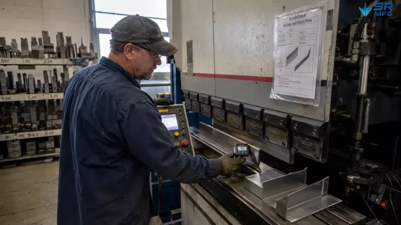
Rückfederungskompensation, Werkzeugauswahl, einschließlich Stempelradius und Matrizenöffnungsbreite, sowie Hinteranschlagprogrammierung werden alle in dieser Phase durchgeführt.
Arbeitsbereich der Abkantpresse nach einer abgeschlossenen Biegung — die digitale Winkelanzeige zeigt 90,1°, die Hinteranschlagfinger halten die Position, und farbcodierte Stempel- und Matrizensätze hängen am Werkzeugregal an der Wand
Phase 5 — Fügen und Montage
- Schweißen Mehrere umgeformte Teile können durch verschiedene Methoden gefügt werden, darunter:
- — MIG-, WIG-, Punktschweißen oder Laserschweißen; häufig für Strukturteile verwendet Nieten und Einbringen von Verbindungselementen — Einschließlich; selbststanzende Muttern und PEM-Einsätze
- ; geeignet für lösbare Baugruppen oder Teile, die für das Schweißen nicht ideal sind Klebeverbindung
Fixture design is especially important at this stage because it helps maintain correct part positioning during joining.
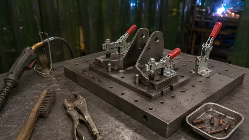
A custom welding fixture positions two formed brackets using machined locating pins and manual toggle clamps — the MIG welding gun waits on its hook while the operator prepares to begin the weld
Stage 6 — Surface Finishing
Depending on the application, parts may go through one or more sheet metal surface finishing processes.
- Deburring and grinding — Removes sharp edges and weld spatter
- Powder coating and liquid painting — Provides corrosion protection and improves appearance
- Anodizing for aluminum, passivation for stainless steel, and galvanizing for carbon steel
Masking requirements, such as protecting specific surfaces or holes from coating, usually need to be considered earlier in the planning stage and reflected in the process flow.
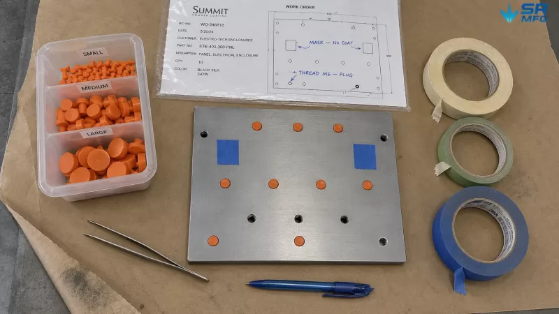
Powder coating masking preparation — silicone plugs seal threaded holes and tape protects mating surfaces, guided by a work order specifying exactly which features must remain uncoated
Stage 7 — Quality Inspection and Testing
Inspection takes place throughout the process. A complete final inspection stage may include:
- Dimensional verification using CMMs, calipers, gauges, or go/no-go gauges
- Sichtprüfung for scratches, dents, coating defects, and other appearance issues
- Funktionstests, such as fit checks or pressure testing, when required
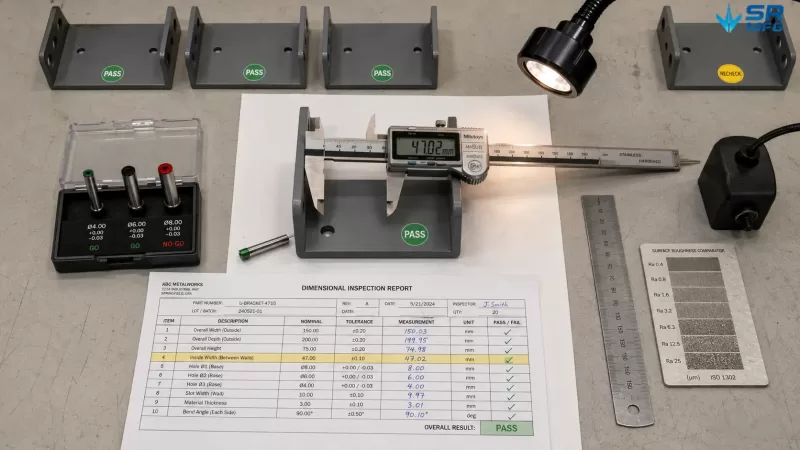
A quality inspection station with a digital caliper measuring a critical bracket dimension, go/no-go pin gauges testing hole diameters, and a completed inspection report recording all measured values
For critical applications, such as aerospace, medical, defense, and other high-requirement industries, a formal Erstmusterprüfung (FAI) may be required before full production, following AS9102 or an equivalent standard.
Stage 8 — Packaging, Logistics, and Delivery
The final step includes protective packaging to prevent coating or finished surface damage, labeling, shipping documentation, and traceability records.
For international shipments, customs documents and material certificates may also be required.
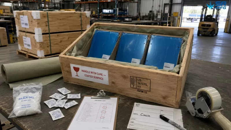
Finished parts packed in cardboard dividers inside a wooden crate, lined with VCI anti-rust paper and desiccant sachets — a handling warning label protects the coated surfaces during transit
Wie Materialien und Design den Prozessfluss verändern
A process flow is not a fixed template. It changes according to the technical requirements of each part, including material type, part geometry, tolerance requirements, production volume, and quality standards.
How Material Changes the Process Flow
Different materials, such as aluminum sheet, stainless steel, and carbon steel, require different cutting parameters, bend radii, and surface preparation methods.
For example, aluminum has lower stiffness and greater springback, so it often requires over-bending compensation and careful tooling selection. Stainless steel work-hardens during forming, which may limit the number of bending operations before annealing is required. Galvanized steel can release harmful fumes during welding, so additional ventilation and safety measures must be included in the welding stage.
How Design Changes the Process Flow
Part design has a direct impact on the number and sequence of operations.
A bracket with bends in four different directions may require four separate press brake setups, while a simple part with bends in only one direction may need just one. Tighter tolerances add more inspection gates. A complex welded assembly may split the process into parallel subassembly branches that merge at the welding stage.
How Production Volume Changes the Process Flow
Production quantity can completely change how the same part is manufactured.
A prototype sheet metal order of five pieces may use laser cutting and simple bending tools, with minimal fixturing requirements. In contrast, a 10,000-piece production run may justify dedicated stamping dies, custom fixtures, and in-line inspection.
For the same part, these two scenarios can result in completely different process flows.
Qualitätskontrolle im Prozessfluss
Quality control is not a separate activity performed only after production is complete. It is built into specific points throughout the manufacturing process.
- Incoming material inspection — Verifies material certificates, thickness, and surface condition before raw material enters production
- Zwischenprüfung — Checks burrs and dimensions after cutting, angles and bend radii after bending, and weld quality after welding through visual inspection, penetrant testing, or ultrasonic testing when required
- Erstmusterprüfung (FAI) — A full dimensional and documentation review, usually performed when a new part enters production or after an engineering change
- Endprüfung — Confirms dimensional accuracy, appearance quality, packaging, and documentation before shipment
When nonconforming parts are found, the process flow defines the handling path: rework, where the part is processed again; concession acceptance, where the part may be accepted with customer approval; or scrap, where the part is rejected and replaced.
This abnormal or “non-standard” path is a critical part of a complete process flow, but it is often overlooked.
Wie der Prozessfluss Kosten, Durchlaufzeit und Beschaffungsentscheidungen beeinflusst
Process Steps Are Cost Drivers
Every step in the process adds cost, including machine time, labor, consumables, and management overhead.
A part that passes through eight operations will usually cost more than a part that passes through five operations, even if both use the same raw material. Understanding this helps purchasing teams determine whether a supplier’s quotation reflects real manufacturing complexity or includes inflated processing costs.
Process Complexity and Lead Time
Sequential steps extend lead time because each operation must wait for the previous one to be completed. Parallel operations can shorten lead time by allowing different tasks to happen at the same time.
Surface finishing and outsourced processes, such as special coatings or heat treatment, are among the most common causes of longer lead times because they introduce external scheduling dependencies.
Supplier Process Questions Purchasing Teams Should Ask
When evaluating a sheet metal fabrication supplier, purchasing teams can ask the following questions:
- “Can you provide the process flow for this part?” — A capable supplier should be able to provide it.
- “Where are your inspection gates in the process?” — This shows how quality is embedded into the process, not merely promised.
- “Which processes are done in-house, and which are outsourced?” — In-house operations usually allow tighter schedule and quality control.
- “How do you handle nonconforming parts?” — The supplier should have a defined process, not a temporary reaction.
- “Is your process flow linked to the control plan?” — This is a sign of a mature quality control system.
Signs of Process Maturity
A well-managed fabrication shop maintains process flows that are documented, version-controlled, and linked to control plans and work instructions.
Warning signs include process knowledge being passed only by word of mouth, key process details existing only in one person’s head, and no traceability between production steps.
A mature process flow makes manufacturing more predictable, measurable, and repeatable, which is especially important for B2B buyers who care about cost control, quality stability, and reliable delivery.
Häufige Fehler und Fallstricke
- Treating the process flow as a one-time document. A process flow is a living system. It must be updated when the design changes, equipment is replaced, or lessons are learned from quality issues.
- Designing only the “normal path.” Ignoring rework loops, scrap handling, and abnormal conditions makes the process incomplete and fragile.
- Too much detail or not enough detail. Recording every small hand movement of an operator creates noise. Missing a critical inspection gate creates risk. The right level of detail depends on the audience and the purpose of the document.
- Creating the process behind closed doors. A process designed only by the engineering team, without feedback from the production line, may miss real manufacturing constraints. Operator involvement is essential.
- Disconnecting the process from other documents. A standalone process flow that is not linked to the control plan, work instructions, or PFMEA has limited practical value.
Beziehung zwischen Prozessfluss und anderen Fertigungsdokumenten
A process flow does not exist in isolation. It is part of a connected manufacturing documentation system.
| Dokument | Umfang | Used By |
|---|---|---|
| Prozessfluss | What happens and in what sequence | All stakeholders, including engineering, production, quality, and purchasing |
| Kontrollplan | What is inspected at each step, which method is used, and how often checks are performed | Quality engineers and inspectors |
| Work Instruction (WI) | Step-by-step operating guidance for a specific process | Production operators |
| Process Failure Mode and Effects Analysis (PFMEA) | Risk analysis of the process flow, including what could go wrong at each step and how it can be prevented | Cross-functional quality teams |
| Process Traveler / Routing Card | Shop-floor execution document used to track a specific production order through each step | Production planners and shop-floor supervisors |
Der process flow is the foundation. Other documents are built on top of its structure. It defines the framework, while related documents add detailed instructions, risk analysis, inspection logic, or execution records.