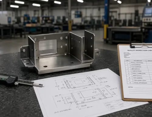
Die Maßprüfung wird oft als “Prüfen eines Teils gegen seine Zeichnung” beschrieben. Diese Beschreibung ist nicht falsch, aber sie ist unvollständig auf eine Weise, die echte Probleme verursacht. Sie verschleiert die Tatsache, dass die Maßprüfung vier verschiedene technische Entscheidungen erfordert — das Verständnis dessen, was die Toleranz tatsächlich bedeutet, die Auswahl eines Messgeräts mit ausreichender Präzision, die Identifizierung der wichtigsten Maße und die Aufzeichnung der Ergebnisse in einer Weise, die einem Streitfall standhält. Wenn eine dieser Entscheidungen versagt, ist das Ergebnis entweder ein gutes Teil, das zurückgewiesen wird, oder ein schlechtes Teil, das akzeptiert wird. Dieser Glossareintrag erklärt, was die Maßprüfung wirklich umfasst, wo die häufigen Missverständnisse liegen und was Ingenieure und Beschaffungsteams wissen müssen, um es richtig zu machen.
Warum “Gut genug” keine Toleranz ist
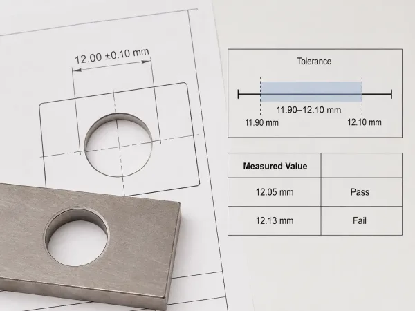
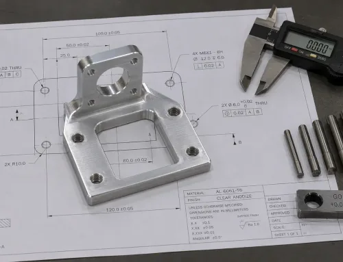
Die Maßprüfung erfordert, dass die gemessenen Werte innerhalb des spezifizierten Toleranzbands bleiben.
Das häufigste Missverständnis über die Maßprüfung ist, dass es sich um ein qualitatives Urteil handelt. Das ist es nicht. Eine Zeichnung, die einen Bohrungsdurchmesser von 12,00 ±0,10 mm angibt, bedeutet genau das: Der gemessene Wert muss zwischen 11,90 mm und 12,10 mm liegen. Ein Messwert von 12,13 mm liegt außerhalb der Spezifikation, selbst wenn das Teil “gut aussieht.”
Der Grund, warum dies wichtig ist, ist einfach. Toleranzen sind keine willkürlichen Zahlen auf einer Zeichnung. Sie sind technische Randbedingungen, die sicherstellen, dass Teile zusammenpassen, Dichtungen Druck halten und Mechanismen sich frei bewegen. Wenn ein Prüfer entscheidet, dass ein Maß “gut genug” ist, übergeht er effektiv die Konstruktionsabsicht des Ingenieurs — oft ohne zu verstehen, warum diese bestimmte Toleranz überhaupt spezifiziert wurde.
Deshalb muss die Maßprüfung quantitative, rückverfolgbare Ergebnisse. liefern. Ein gemessener Wert zusammen mit einem Toleranzband liefert eine klare Fertigungsabnahmekriterien für eine Bestehens- oder Nichtbestehensentscheidung. “Sieht gut aus” tut das nicht.
Das richtige Werkzeug wählen: Die 10:1-Regel und wann was verwendet wird
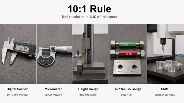
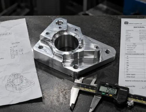
Messwerkzeuge sollten eine ausreichend feine Auflösung für die zu prüfende Toleranz bieten.
Eine der praktischsten Fragen in der Maßprüfung ist, welches Messinstrument verwendet werden soll. Die 10:1-Regel bietet einen Ausgangspunkt: Die Auflösung Ihres Instruments sollte mindestens ein Zehntel der Toleranz betragen, die Sie prüfen. Für eine ±0,10 mm Toleranz, bedeutet das eine Auflösung von 0,01 mm oder besser. Einige Branchen und Normen verwenden andere Verhältnisse — 4:1 wird manchmal als Minimum genannt, während 20:1 für kritische Messungen bevorzugt wird — aber das Prinzip ist dasselbe: Wenn Ihr Werkzeug nicht deutlich präziser ist als die Toleranz, kann die Messunsicherheit selbst einen Zustand außerhalb der Spezifikation verschleiern.
Handwerkzeuge: Messschieber, Mikrometer und Höhenmessgeräte
Digitale Messschieber (Auflösung 0,01 mm) sind das vielseitigste Handinstrument für allgemeine Maße — Gesamtlänge, Breite, Lochdurchmesser, Stufenhöhe. Sie sind gut geeignet für Toleranzen von ±0,10 mm oder lockerer. Außenmikrometer (Auflösung 0,001 mm) bieten eine bessere Präzision für engere Merkmale wie Bohrungs- oder Wellendurchmesser. Höhenmessgeräte, verwendet auf einer Messplatte, messen Stufenhöhen und auf Bezugselemente referenzierte Merkmale mit ähnlicher Präzision.
Gauges: go/no-go pins, thread gauges, and profile gauges
Go/no-go pins and thread gauges provide a fast pass/fail check for holes and threads without returning a numerical value. They are efficient for production environments where the question is simply “in spec or not.” Profile gauges check whether a surface or contour falls within a tolerance band. The limitation of attribute gauges is that they do not tell you how close to the limit a feature is — only whether it passed.
CMMs and when hand tools are not enough
When tolerances are tighter than ±0.01 mm, or when the part has complex geometry with many interrelated dimensions, coordinate measuring machines (CMMs) become the appropriate tool. A CMM uses a touch probe to capture 3D coordinates and can achieve measurement accuracies down to ±0.005 mm or better. CMMs are especially valuable for parts with profile tolerances, position callouts, or features that are difficult to access with hand tools.
A practical Qualitätskontrolle und Inspektion framework uses calipers for tolerances at ±0.10 mm or looser, micrometers and gauges for tolerances between ±0.05 and ±0.01 mm, and a CMM for anything tighter or geometrically complex. When in doubt, verify that your tool’s resolution is at least 10 times finer than the tolerance band.
Nicht jedes Maß ist kritisch — So unterscheidet man sie
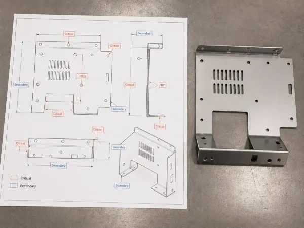
Critical dimensions control fit and function, while secondary dimensions can usually be sampled less frequently.
A typical drawing may contain dozens of dimensions. Treating all of them with equal priority wastes inspection time and obscures the dimensions that actually control fit and function. The practical distinction is between critical dimensions and secondary dimensions.
Kritische Maße are those that directly affect assembly, sealing, structural integrity, or mechanical function. On a sheet metal part, these typically include:
- Mounting hole positions relative to a datum
- Bend angles and flange lengths on formed features
- Mating surface lengths and widths
- Feature-to-feature distances that determine fit with adjacent parts
These dimensions should be prioritized during inspection — checked on every part or with tight sampling plans. Secondary dimensions include outer edge profiles, cosmetic cutouts, non-functional radii, and features with loose general tolerances. They can be sampled less frequently without compromising the integrity of the inspection.
The reason this distinction matters is practical. Inspection resources are finite. When a supplier’s inspection plan checks every dimension to the same standard, it either takes too long or spreads attention too thin. A better Blechprüfplan focuses inspection effort on the dimensions where failure would actually affect the part’s function — and communicates which dimensions are critical in the drawing or purchase order.
Prüfaufzeichnungen: Was enthalten sein muss und warum sie wichtig sind
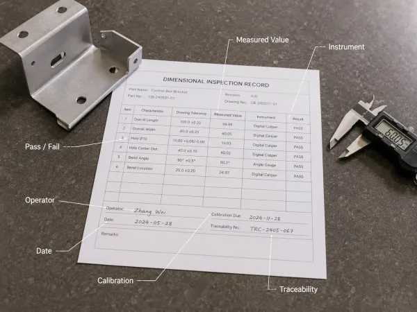
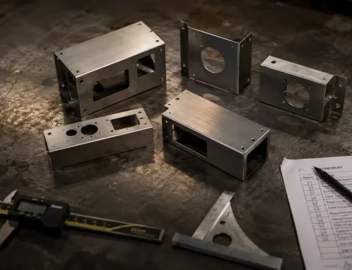
A complete inspection record should include measured values, instrument details, calibration status, traceability, and pass or fail results.
The inspection record is the only objective evidence that a part met specification at the time of delivery. When a dimensional dispute arises — a part does not fit, a customer rejects a shipment, an auditor asks for proof — the record is what settles it. Without it, measurements cannot be traced back to a specific batch or operator, and pass or fail determinations become one person’s word against another’s.
A complete inspection record should include:
- Measured value with units (e.g., 12.05 mm, not just “pass”)
- Instrument used — type and identifier (e.g., Mitutoyo digital caliper, ID# C-042)
- Calibration status — confirmation that the instrument was within its calibration period
- Operator name
- Date of inspection
- Rückverfolgbarkeit — lot number, serial number, or work order reference
- Pass or fail determination against the specified tolerance
For procurement teams, the most effective way to ensure complete records is to define the Fertigungsqualitätsanforderungen upfront. Include inspection expectations in your RFQ and drawings: identify which dimensions are critical, state the acceptance criteria, specify the report format you expect, and ask for instrument and calibration references. Clear requirements at the RFQ stage prevent the most common inspection-related disputes: disagreements over which dimensions were supposed to be checked, uncertainty about whether the right tool was used, and missing evidence when parts are rejected.
Was Blechteile unterscheidet
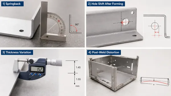
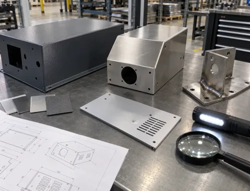
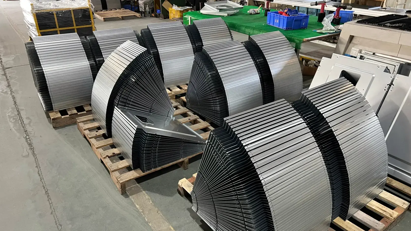
Sheet metal inspection must consider springback, hole shift after forming, thickness variation, and post-weld distortion.
Sheet metal fabrication introduces dimensional challenges that do not exist with machined parts. Understanding these challenges is the difference between an inspection plan that works and one that generates false rejects or passes bad parts.
Bend angle springback. When sheet metal is bent, the material springs back slightly after the press brake releases. A 90° bend specified on the drawing may come off the press at 88° or 91°, depending on material type and thickness, bend radius, tooling setup, and whether the press brake is CNC-controlled or manual. The achievable tolerance depends on these factors — not just what the drawing says.
Hole location accuracy after forming. Holes punched or drilled before bending shift position during the forming operation. When a part has multiple holes in different bend zones, the accumulated positional error can be significant. This is why hole-to-hole and hole-to-edge dimensions on formed parts require special attention during inspection.
Material thickness variation. Sheet stock comes with its own thickness tolerance — a nominal 1.5 mm sheet might measure anywhere from 1.42 to 1.58 mm depending on the standard and supplier. This variation affects bend radius, the resulting angle, and the overall height of formed features. It should be accounted for in the inspection plan.
Post-weld distortion. Welded assemblies can distort from residual stress, shifting dimensions away from their pre-weld values. The inspection plan should account for post-weld variation, not just the nominal geometry.
Sheet metal dimensional inspection requires judgment — understanding which tolerances are achievable with the forming process, not just checking numbers against a drawing.
Wichtige Erkenntnisse
- Dimensional inspection is quantitative measurement with traceable results. “Looks good” is not an inspection.
- The 10:1 rule guides instrument selection: your tool’s resolution should be at least one-tenth of the tolerance you are checking.
- Not every dimension is equally important. Focus inspection effort on critical dimensions — those that drive assembly and function.
- Inspection records are the evidence that resolves disputes. Specify what you need in your RFQ and drawings, not after delivery.
- Sheet metal parts have their own inspection challenges — springback, hole shift after forming, material thickness variation, and post-weld distortion — that require manufacturing judgment, not just numerical comparison.
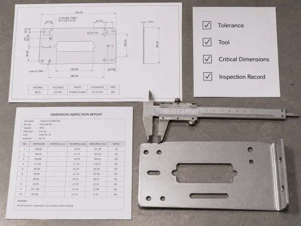
A practical dimensional inspection review should confirm tolerance, tool selection, critical dimensions, and traceable records.