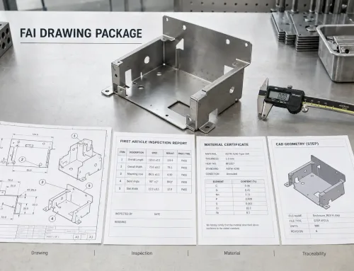
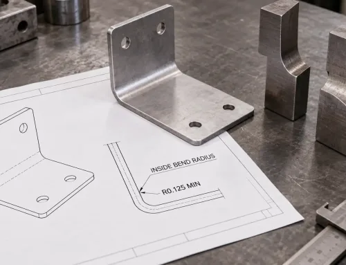
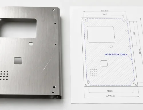
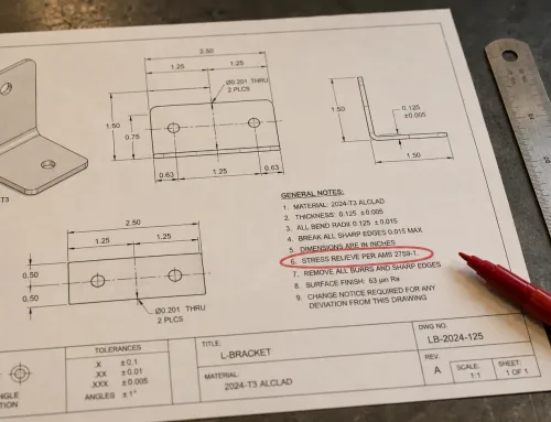
WWas muss Ihr Blechlieferant auf Ihren Zeichnungen sehen? Was passiert, wenn diese Informationen fehlen?
Wenn ein kundenspezifischer Blechfertigungsanbieter Ihr Zeichnungspaket erhält, beginnt er nicht sofort mit dem Laserschneiden oder Biegen. Der erste Schritt ist die Bewertung, ob die Dateien vollständig sind.
Ein vollständiges Paket mit einem 3D-CAD-Modell, einer 2D-Zeichnung und den korrekten Dateiformaten ermöglicht eine schnellere Kalkulation und eine genauere Fertigung. Unvollständige Dateien können Angebote verzögern und in manchen Fällen zu Ausschussteilen führen.
Was unterscheidet Blechzeichnungen von anderen Zeichnungen?
Blechteile werden nicht aus Vollmaterialblöcken gefräst. Sie werden aus flachen Blechen durch mehrere Fertigungsprozesse geformt. Dieser Unterschied beeinflusst, wie Blechzeichnungen erstellt und interpretiert werden.
Eine Standard-CNC-Bearbeitungszeichnung konzentriert sich hauptsächlich auf die Maßtoleranzen und die Oberflächenbeschaffenheit eines Vollteils. Blechzeichnungen müssen zusätzliche Fertigungsinformationen vermitteln.
Zusätzlich zu den Fertigmaßen sollten Blechfertigungszeichnungen eine Abwicklung zeigen, die die Form vor dem Biegen darstellt, sowie Biegelinien mit Richtungsangaben, Biegewinkel und Biegeradien. In manchen Fällen muss auch die Walzrichtung des Materials angegeben werden.
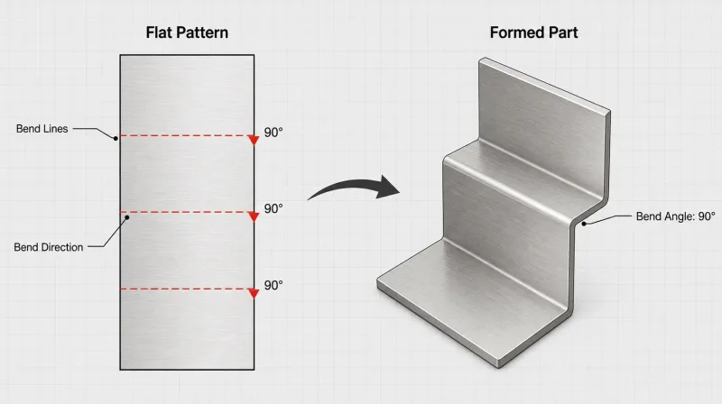
Dieses Diagramm zeigt, wie sich ein flaches Blech (links) mit Biegelinien nach dem Biegen in eine fertige 3D-Halterung (rechts) verwandelt. Die Biegelinien, Biegerichtungspfeile und Biegewinkel sind auf der Abwicklung beschriftet — die entscheidenden Details, die Blechzeichnungen von Standard-Bearbeitungszeichnungen unterscheiden.
Diese Details finden sich normalerweise nicht auf Zeichnungen für konventionelle prismatische Bearbeitungsteile, und ihr Fehlen ist eine häufige Ursache für Fertigungsverzögerungen.
Die Rollen von 2D-Zeichnungen, 3D-Dateien und PDFs
Nur einen Dateityp einzureichen — ob eine 2D-Zeichnung oder ein 3D-Modell — ist für die Blechfertigung in der Regel nicht ausreichend. Jede Datei erfüllt einen anderen Zweck im Fertigungsworkflow. Der effizienteste Ansatz ist, alle drei zusammen zu verwenden.
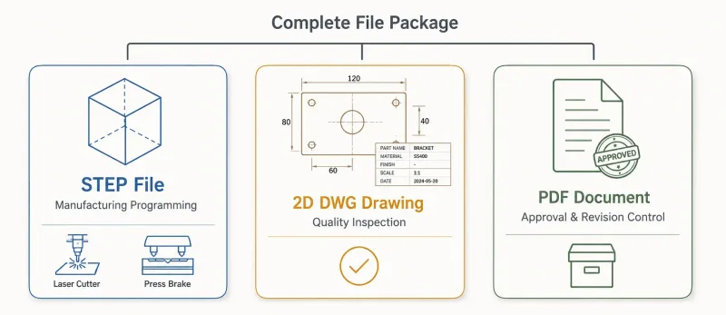
Dieses Diagramm veranschaulicht die unterschiedlichen Rollen von drei Dateitypen in der Blechfertigung: Die 3D-STEP-Datei steuert die Fertigungsprogrammierung (Laserschneiden, Biegen), die 2D-DWG-Zeichnung definiert die Qualitätsprüfanforderungen, und das PDF dient als Referenzdokument für Freigabe und Revision. Die Verwendung aller drei zusammen gewährleistet die schnellste Kalkulation und die genaueste Produktion.
Zweck von 3D-CAD-Dateien
Ein 3D-Modell, das dem Blechfertigungsbetrieb üblicherweise im STEP-Format bereitgestellt wird, ist die Grundlage der modernen Blechprogrammierung.
Der Fertigungsbetrieb kann die 3D-Datei nutzen, um Folgendes zu beginnen:
- Generierung von Laserschneidbahnen
- Berechnung von Abwicklungen durch automatisches Abwickeln
- Optimierung der Materialausnutzung durch Nesting
- Generierung von CNC-Gesenkbiegeprogrammen
Ohne eine 3D-Datei muss der Fertigungsbetrieb möglicherweise die Geometrie aus der 2D-Zeichnung rekonstruieren, was zeitaufwändig und fehleranfällig ist.
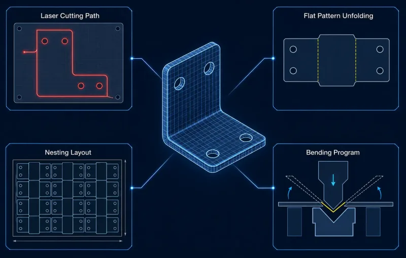
Eine 3D-STEP-Datei ermöglicht vier wichtige Fertigungsschritte: Generierung von Laserschneidbahnen, automatisches Abwickeln des Teils in eine flache Abwicklung, Optimierung der Materialausnutzung durch Nesting und Generierung von Biegeprogrammen. Ohne diese Datei muss der Fertigungsbetrieb die Geometrie manuell aus 2D-Zeichnungen rekonstruieren — ein langsamerer und fehleranfälliger Prozess.
Zweck von 2D-Zeichnungen
Obwohl der Fertigungsprozess durch die 3D-Datei gesteuert wird, definiert die 2D-Zeichnung die Abnahmeanforderungen.
Die folgenden Informationen sollten auf der 2D-Zeichnung dargestellt werden:
- Kritische Maße
- Geometrische Toleranzen
- Oberflächenbeschaffenheitsspezifikationen
- Angaben zu Einbauteilen
- Montagebezugspunkte
Qualitätsprüfer verlassen sich auf diese Zeichnungen, um das fertige Teil zu verifizieren. Die 2D-Zeichnung fungiert daher als verbindliches Dokument zwischen dem Bestellten und dem Gelieferten.
Ein 3D-Modell allein kann nicht vollständig angeben, welche Maße für die Montage kritisch sind und welche nur als Referenz dienen.
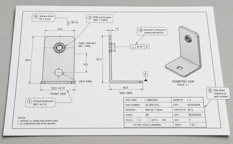
Eine gut vorbereitete 2D-Blechzeichnung sollte klar beschriftete kritische Maße mit Toleranzen, Oberflächenbeschaffenheitsspezifikationen, Angaben zur Montage von Einbauteilen, Montagebezugspunkte und einen vollständigen Schriftkopf enthalten. Dieses kommentierte Beispiel zeigt jedes wesentliche Element, auf das sich Qualitätsprüfer verlassen, um das fertige Teil zu verifizieren.
Zweck von PDF-Dateien
PDF-Dateien werden nicht für die Fertigungsprogrammierung verwendet. Ihr Zweck ist Dokumentenmanagement, Revisionskontrolle, Freigabeverfolgung und Archivierung.
Obwohl ein Design mehrere Revisionen durchlaufen kann, wird nur das unterzeichnete und freigegebene PDF als Produktionsreferenz verwendet.
Viele Blechfertigungsbetriebe akzeptieren PDFs als unterstützende Dokumente, aber sie werden normalerweise kein Teil allein auf Basis eines PDFs kalkulieren oder fertigen, wenn kein 3D-Modell oder keine 2D-Zeichnung verfügbar ist.
Dateipriorität festlegen
Bei der Einreichung von Dateien ist klar zu kennzeichnen, welches Dokument die Produktion und Inspektion steuert.
Ein üblicher Ansatz ist:
- Eine revisionskontrollierte 2D PDF defines tolerances, materials, surface finishes, and inspection requirements
- Der STEP model defines the nominal 3D geometry
- Der DXF communicates the approved 2D cutting profile
- Flat patterns generated by the fabricator are supplier process files
If the 2D drawing, 3D model, and DXF conflict, the discrepancy should be confirmed in writing before quotation or production. The machine operator should not be expected to choose which file to follow.
Choosing the Correct File Formats
The file formats you submit determine how efficiently the sheet metal fabricator can process your design.
The table below summarizes the most common formats used in sheet metal fabrication.
| Format | File Type | Main Use | Hinweise |
|---|---|---|---|
| STEP (.stp, .step) | 3D | Manufacturing programming, flat-pattern calculation, nesting optimization | Universal 3D exchange format; preferred by most fabricators |
| DXF (.dxf) | 2D | Laser-cutting profiles and flat-pattern outlines | Suitable for simple flat parts or 2D cutting profiles |
| DWG (.dwg) | 2D | Dimensioned drawings and tolerance callouts | Native AutoCAD format; widely supported |
| PDF (.pdf) | 2D reference | Approval records and revision reference | Not used for manufacturing programming |
For many sheet metal projects, the recommended combination is a STEP file for the 3D geometry and a dimensioned PDF or DWG for the 2D specifications.
For a simple flat profile that requires no bending, a single DXF file may be sufficient.
Information Every Sheet Metal Drawing Must Include
A complete sheet metal drawing must tell the fabricator four things:
- What shape must be cut?
- How must it be bent?
- What material must be used?
- How must the finished part be verified?
Each requirement must be communicated through specific information on the drawing.
Views and Layout
A sheet metal drawing should include at least:
- Front view
- Side view
- Isometric view
- Flat pattern
The front and side views show the formed geometry.
The isometric view provides a visual reference.
The flat pattern shows the shape before bending.
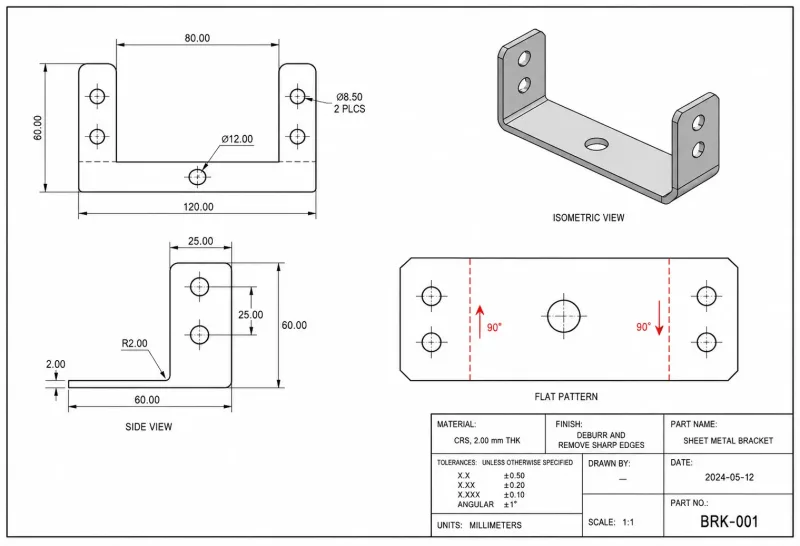
A complete sheet metal drawing should include at least four views: a front view and side view showing the formed geometry, an isometric view for visual reference, and a flat pattern showing the part’s shape before bending. The isometric view is especially important for complex parts where multiple bends interact.
The isometric view is particularly important for complex parts because it resolves details that orthographic projections may not clearly communicate, especially when several bends interact.
Required Title Block Information
The title block is one of the first areas reviewed by the fabricator. It should include:
- Material grade and sheet thickness: 304 stainless steel, 1.5 mm
- Oberflächenbehandlung: powder coating, RAL 7035, 60–80 μm
- Required quantity
- Part number and revision
- Applicable tolerance standard: ISO 2768-mK
Maße und Toleranzen
Dimensions on sheet metal drawings should follow standard engineering drawing practices:
- Clearly identify reference dimensions
- Apply explicit tolerances to critical features
- Avoid redundant dimensions
When tolerances are not specified, the fabricator may apply general tolerances based on the material and manufacturing process.
Common reference values include:
- Laser cutting: ±0,1 mm
- Each bend: ±0,3 mm
- Hole diameter: ±0,05 mm
- Overall length: ±0.2 mm per metre
These general values do not replace explicit tolerances on critical features.
Specifying Surface Finishes and Secondary Operations
Sheet metal parts often require processes beyond cutting and bending.
Welding, hardware installation, tapping, and sheet metal surface finishing are common secondary operations. Each must be clearly specified on the drawing to prevent manufacturing errors.
Schweißen
When a part requires welding, the drawing should identify the weld location and weld type.
It should state whether the part requires:
- Punktschweißen
- Continuous full welding
- WIG-Schweißen
- Specific appearance or dimensional quality requirements
For assemblies containing multiple parts, a separate assembly drawing should be provided to show weld locations.
Hardware Installation
Self-clinching fasteners, such as PEM studs, nuts, and standoffs, are widely used in sheet metal assemblies.
The drawing should specify:
- Fastener type
- Standard part number
- Installation location
- Installation direction
- Protruding or flush requirements
Calling out the PEM or equivalent standard part number directly on the drawing eliminates guesswork and prevents incorrect installation.
Tapping and Threads
Thread specifications should include:
- Thread size and pitch
- Thread depth
- Location on the part
Zum Beispiel: M3 × 0.5.
Blind threaded holes require particular attention. The sheet metal fabricator must know the minimum thread engagement depth to select the correct tap and prevent it from bottoming out.
Oberflächenveredelung
Surface finish callouts must be specific. Simply writing “paint” or “coating” is not sufficient.
A complete specification should include:
- Coating thickness range, such as 60–80 μm
- Surfaces to be coated
- Masking requirements
For anodizing, specify:
- Type II: decorative
- Type III: hard anodizing
- Colour and thickness class
Common Drawing Errors That Delay Quotations
The following issues are frequently identified during sheet metal RFQ reviews.
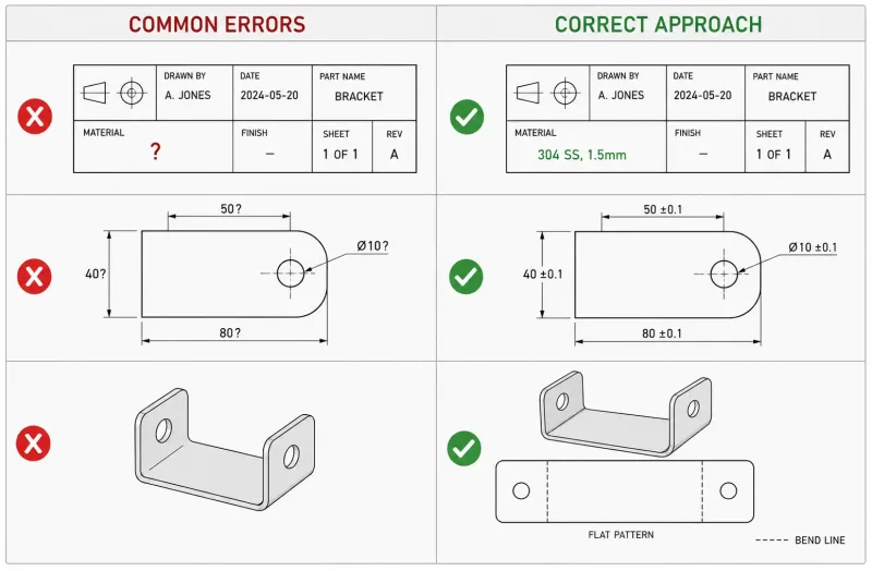
Six common drawing errors that delay sheet metal quotations: missing material specification, missing critical tolerances, no flat pattern or bend callouts, vague surface finish descriptions, unspecified bend direction, and missing assembly files for multi-part projects. Each error is shown alongside its correct version for quick reference.
| Common Problem | Effect on the Quotation |
|---|---|
| Material grade or sheet thickness not specified | Material cost and stock availability cannot be confirmed |
| Critical dimensions have no tolerances | The engineering team must request clarification or make assumptions that may not reflect the design intent |
| No flat pattern or bend callouts | The fabricator must regenerate the flat pattern from the 3D model and confirm the bending details, adding 1–3 days |
| Surface finish described with only one word, such as “paint” | Coating type, colour, and thickness must be confirmed before quotation |
| Bend direction not specified | There is a risk of bending in the wrong direction, requiring the engineering team to infer and confirm the correct orientation |
| No assembly file for a multi-part project | Part relationships, fit requirements, and assembly sequence cannot be determined |
Most of these issues can be avoided with a few minutes of checking before submitting the RFQ.
How File Requirements Change from Prototypes to Production
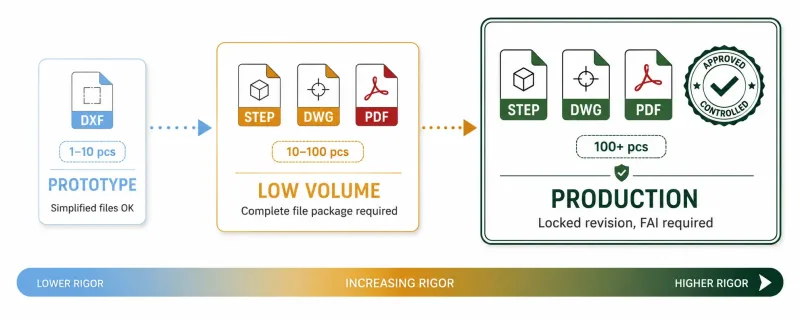
File requirements become more rigorous as projects move from prototype (1–10 pieces, simplified files accepted) through low-volume (10–100 pieces, complete file package required) to production (100+ pieces, drawings serve as formal manufacturing control documents with locked revisions).
Prototype Stage: Typically 1–10 Pieces
At the prototype stage, the fabricator may accept simplified files, such as a basic dimensioned 2D DXF or a STEP file accompanied by brief written instructions.
Speed is the priority, and both parties understand that some details may be confirmed verbally.
However, this flexibility introduces risk. Without formal documentation, the finished part may differ from the designer’s intent.
Low-Volume Stage: 10–100 Pieces
At this stage, a complete file package must be submitted.
It should include:
- A 3D model
- A fully dimensioned 2D drawing
- Toleranzen
- Materialspezifikationen
- Anforderungen an die Oberflächenbeschaffenheit
Verbal confirmations should now be replaced by written drawing callouts.
Production Stage: More Than 100 Pieces
At this stage, drawings should be used as manufacturing control documents.
They should include:
- Sheet metal First Article Inspection requirements
- Packaging specifications
- A locked revision number
Any design change should be incorporated into the drawings through a formal revision process before the next production run.
Pre-Submission Checklist
Before sending files to a sheet metal fabricator, confirm that the following information is complete.
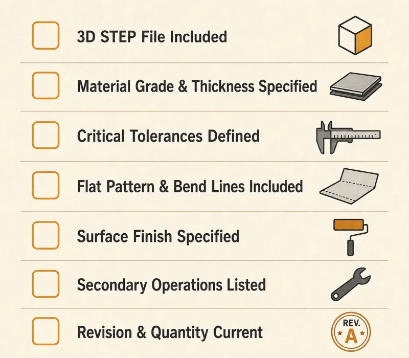
Before sending files to a sheet metal fabricator, verify that all seven checklist items are complete: 3D STEP file included, material and thickness specified, critical tolerances defined, flat pattern with bend details included, surface finish fully specified, secondary operations listed, and revision and quantity confirmed as current.
| Checklist Item | What to Confirm |
|---|---|
| 3D file included | STEP or STP format; individual part file rather than an assembly, unless an assembly quotation is required |
| Material specified | Alloy grade and sheet thickness shown in the title block or BOM, such as AA 5052-H32 Aluminium, 2.0 mm |
| Critical tolerances defined | Assembly dimensions, hole positions, mating surfaces, and other critical features have explicit tolerances |
| Flat pattern included | Bend lines, bend directions, and bend angles are shown for all formed features |
| Surface finish specified | Colour, coating type, film thickness, and coated surfaces are defined |
| Secondary operations specified | Weld locations, hardware types, thread specifications, and special processes are listed |
| Revision and quantity are current | The title block shows the latest revision and correct order quantity |
This checklist does not replace the fabricator’s engineering review, but it helps ensure that your files are complete enough for the review to begin without delay.
How SR-MFG Supports Your RFQ Process
The SR-MFG engineering team reviews every drawing package before quotation to check its completeness and manufacturability.
The review covers:
- Material and sheet thickness verification
- Flat-pattern accuracy
- Bending feasibility
- Tolerance analysis
- Identification of all secondary operations
If information is missing, the team contacts you about the specific issue rather than returning the entire package. This reduces repeated communication, shortens engineering confirmation time, and helps keep the project on schedule.
To submit a sheet metal RFQ, send your 2D drawings, 3D CAD files, material and surface finish specifications, required quantity, and any special requirements to the SR-MFG engineering team.