Serienfertigung von Blechbauteilen Dienstleistungen

Mit über 10 Jahren praktischer Erfahrung in der Blechbearbeitung unterstützt SR MFG Teile und Baugruppen, die eine langfristige, wiederholbare Versorgung erfordern – gestützt auf skalierbare Produktion für die Serienfertigung.
Produktionsangebot anfordern
NDA verfügbar
DFM-Prüfung inklusive
STEP / DXF / PDF akzeptiert
Angebot in 24–48 Stunden
000+ Stück

Optimiert für mittlere
bis hohe Stückzahlen

Dedizierte Werkzeuge

Niedrigere Stückkosten durch
zweckgebundene Werkzeuge

Stabile Wiederholbarkeit

Gleichbleibende Qualität über
jede Charge hinweg

Chargenrückverfolgbarkeit

Vollständige Losrückverfolgbarkeit &
Dokumentation

Was ist die Serienfertigung von Blechbauteilen?
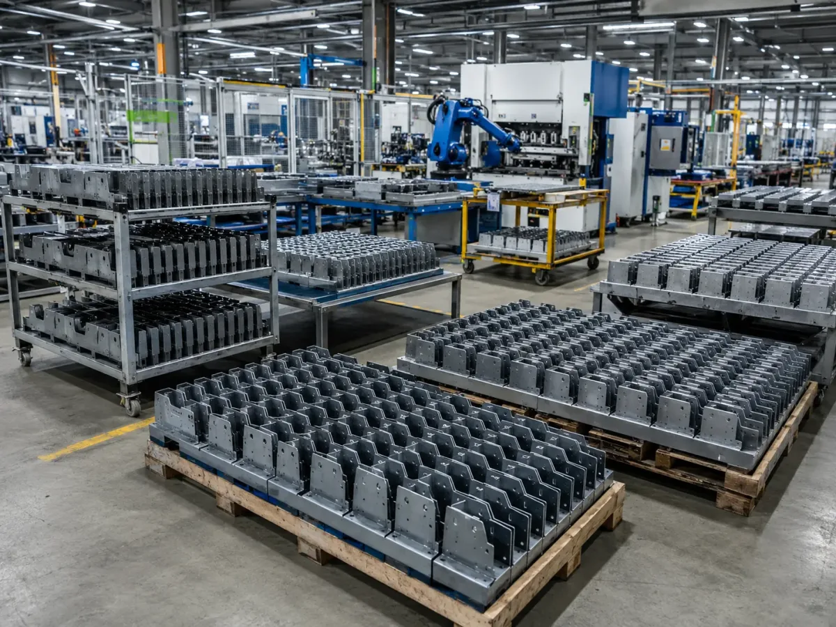
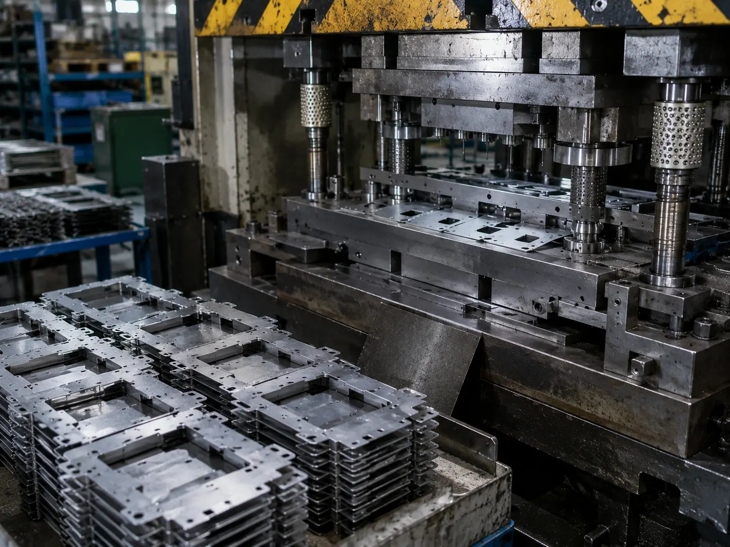
High-volume sheet metal manufacturing with standardized batch production and repeatable output

Die Serienfertigung von Blechbauteilen bezeichnet typischerweise die kontinuierliche, standardisierte, großmaßstäbliche Produktion von Dünnblech – wobei häufig ~6 mm als praktische Trennlinie zwischen Blech und Platte, dient, je nach Anwendung.

Sobald die Zeichnungsrevision stabil ist und Änderungen gut kontrolliert werden, verlagert sich die Produktion in der Regel hin zu einem stärker linienbasierten, automatisierungsgesteuerten Ansatz– mit dedizierten Vorrichtungen, Taktzeit-Operationen und, wo sinnvoll, werkzeugbasierten Verfahren. Die Kernziele bei Serienprogrammen sind höherer Durchsatz, niedrigere Stückkosten (durch Verteilung der Vorabinvestition auf mehr Teile) und gleichbleibendere Ergebnisse von Charge zu Charge.

Welche Projekttypen erfordern Serienfertigung von Blechbauteilen?

Der Schlüssel liegt nicht nur in “mehr Teilen” – sondern darin, das Programm auf einen wiederholbaren Rhythmus und gleichbleibenden Output. zu bringen. Wenn Nachfrage und Revisionen stabil sind, können Sie Automatisierung, dedizierte Vorrichtungen/Werkzeuge und standardisierte Operationen nutzen, um kontinuierlich große Mengen identischer – oder hochgradig ähnlicher – Teile und Baugruppen zu produzieren, mit einem auf die Nachfrage abgestimmten Produktionstempo (oft gesteuert über Taktzeit).
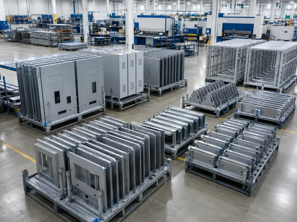
High-volume sheet metal projects including enclosures, panels, guards, frames, and OEM assemblies

Am besten geeignete Projekte für die Serienfertigung
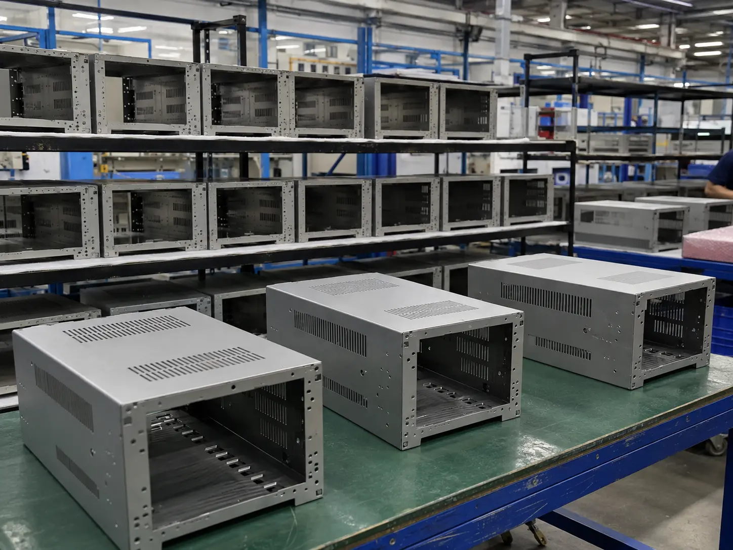
High-volume electronics enclosures and metal housings

Elektronikgehäuse

Racks, Gehäuse, Schaltkästen, Paneele
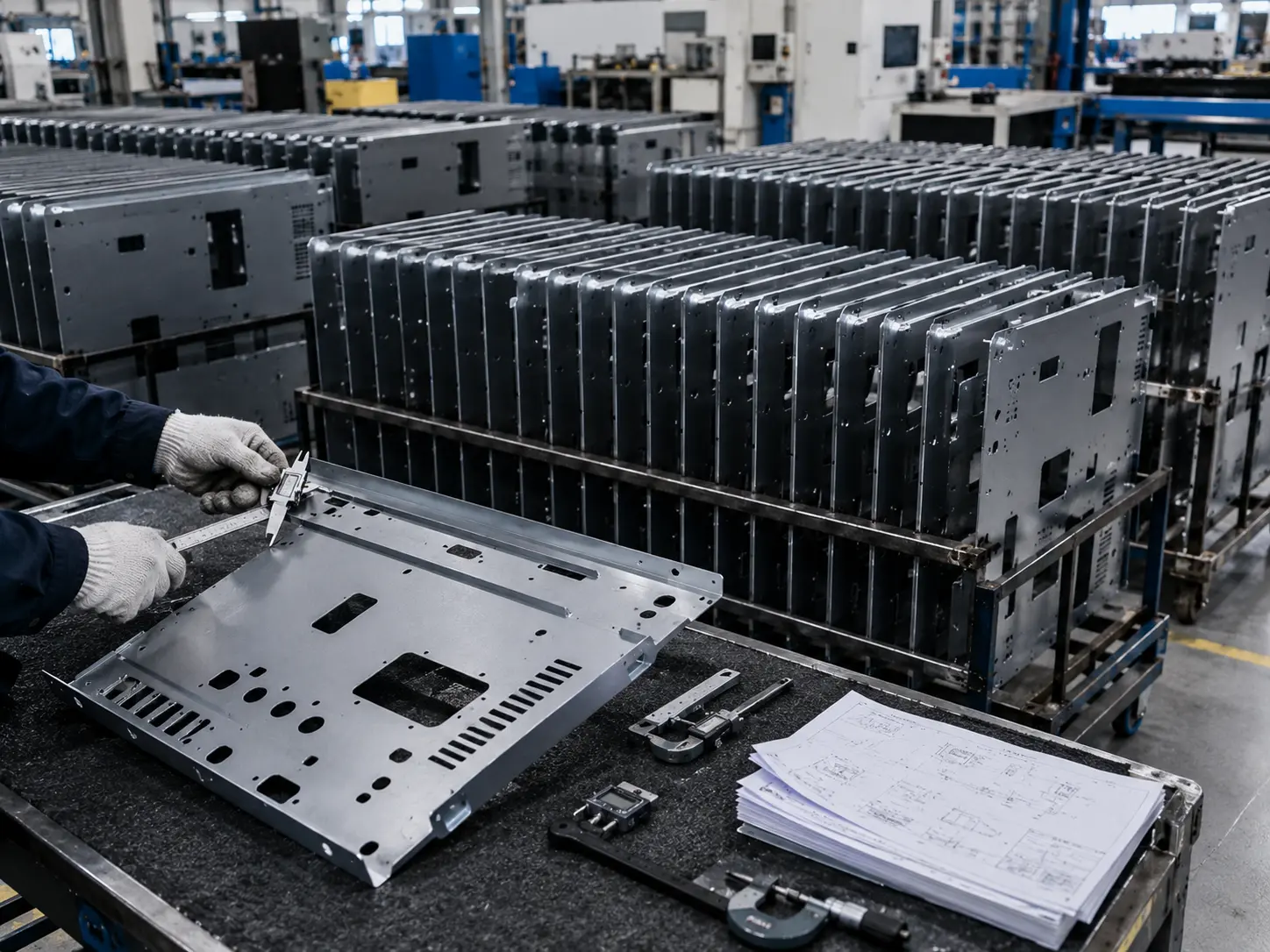
High-volume automation equipment panels and mounting plates

Automatisierungsgeräte-Paneele

Schalttafeln, Seitenbleche, Montageplatten, Halterungen
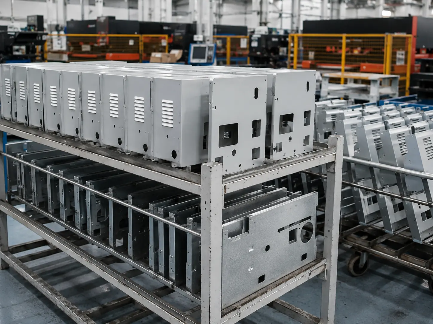
High-volume machine covers guards and access panels

Maschinenabdeckungen & Schutzbleche

Schutzbleche, Verkleidungen, Zugangsbleche, belüftete Abdeckungen
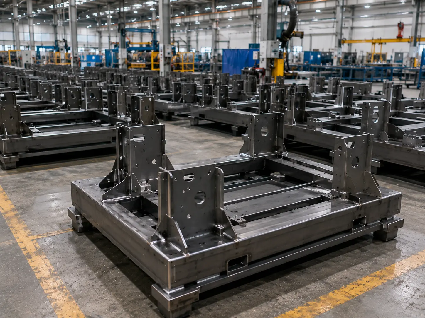
High-volume welded structural frames and machine bases

Strukturrahmen & Grundplatten

Geschweißte Rahmen, Grundplatten, Stützstrukturen, Maschinenfundamente
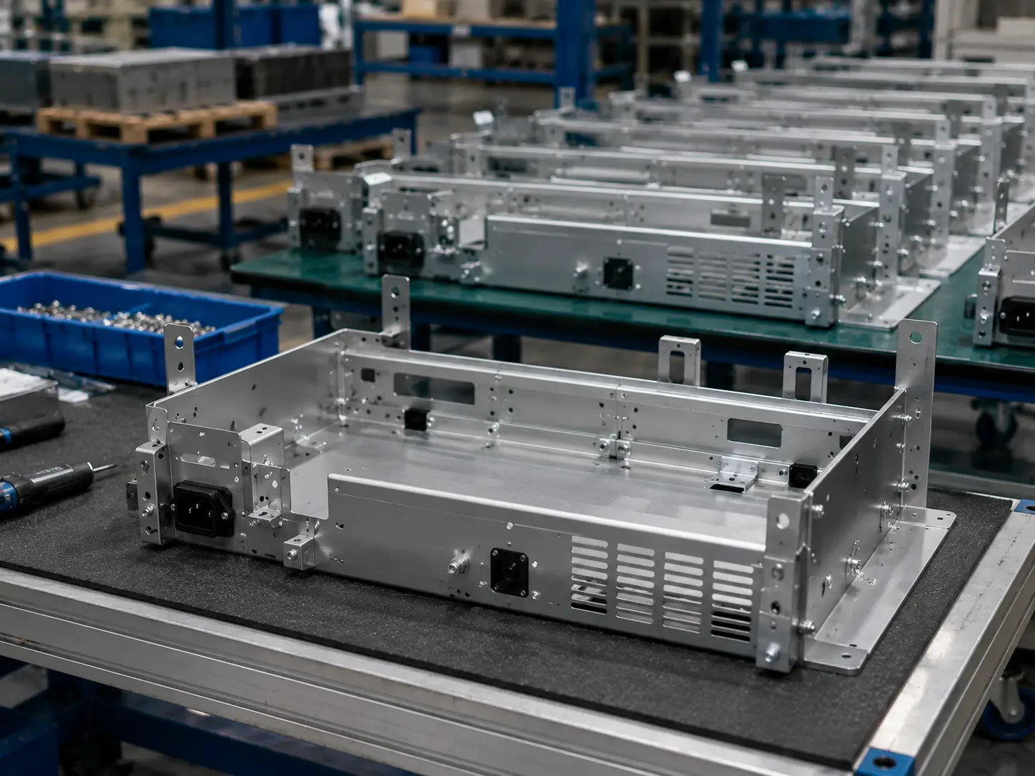
Repeat OEM sheet metal assemblies and chassis components

Wiederkehrende OEM-Baugruppen

Halterungen, Baugruppen, Chassiskomponenten, Wiederholteile

Wie Sie feststellen, ob Ihr Projekt zu einem Hochvolumenmodell passt

(Je mehr Übereinstimmungen, desto besser die Eignung.)

  • 1

    Zeichnungen wiederholen sich stark und Sie benötigen langfristige rollierende Lieferung

  • 2

    Revisionen sind stabil und technische Änderungen sind selten

  • 3

    Sie sind stückkostenempfindlich und bereit, Werkzeuge/Vorrichtungen gegen niedrigere Langlaufkosten einzutauschen (Skaleneffekte)

  • 4

    Sie benötigen hohe Austauschbarkeit und Baugruppen-zu-Baugruppen-Konsistenz

  • 5

    Sie benötigen einen gleichmäßigeren Takt mit weniger Umrüstvorgängen – ideal für linienbasierte Organisation
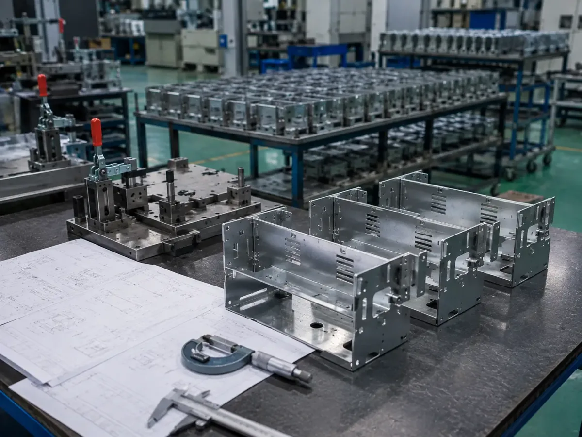
Repeat sheet metal parts, fixtures, and drawings used to evaluate high-volume production readiness
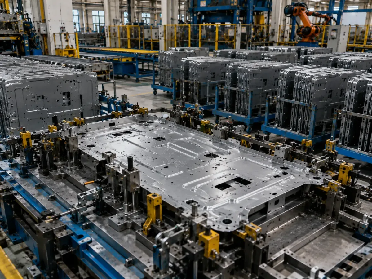
Sheet metal part positioned in dedicated tooling for repeatable high-volume production

Warum diese Projekte zu Hochvolumen-Blechbearbeitung passen

Denn Skalierung bedeutet nicht “Mengen stapeln” – es geht darum, Unsicherheit im Vorfeld zu beseitigen:

Revisionen einfrieren → CTQs (Critical-to-Quality-Merkmale) definieren → Schlüsseldatums mit Vorrichtungen/Werkzeugen/Formen fixieren → Operationen auf einen wiederholbaren Takt standardisieren– sodass Sie bei steigenden Stückzahlen konsequent besseren Durchsatz und niedrigere Stückkosten erzielen.

Wie wählen Sie die richtige
Produktionsprozessroute?

Wir empfehlen eine Fertigungsroute basierend auf Ihrem Jahresvolumen, CTQs.

1

Während aktiver Revisionszyklen

Verwenden Sie eine flexible Route mit Laserschneiden / CNC-Revolverstanzen + Gesenkbiegen.

Ideal für häufige Revisionen und schnellere Validierung.

2

Während der Hochlaufphase

Führen Sie dedizierte Vorrichtungen und Arbeitszellen ein, um Taktzeit und Konsistenz frühzeitig zu fixieren.

3

Sobald das Design eingefroren ist und die Nachfrage stabil ist

Bewerten Sie Hochdurchsatzrouten wie Stanzen, Rollformen oder Tiefziehen zur Reduzierung der Stückkosten.

Vergleich der Produktionsrouten

Produktionsroute Typische Prozesskombination Am besten geeignete Produktionsphase Vorabinvestition
(Formen/Vorrichtungen)
Stückkostenprofil Wesentliche Design-/Prozesseinschränkungen
Flexibel
Route
Laser / CNC-Revolverstanzen + Biegen + Universal-Schweißen/Montage Niedriges bis mittleres Volumen; häufige Revisionen Niedrig Stückkosten steigen schnell mit zunehmender Operationsanzahl Loch-zu-Biege-Regeln, Toleranzkumulierung, Schweißverzug; optische Konsistenz erfordert oft Vorrichtungsunterstützung
Halbwerkzeuggebunden
Route
CNC-Revolverstanzen inkl. Umformen / Laser + dedizierte Vorrichtungen + zellenbasierte Montage Mittleres bis höheres Volumen; stabile Struktur Mittel Stabilerer Takt; Kosten können im Laufe der Zeit gesenkt werden CTQs need to be frozen earlier; fixture strategy sets the ceiling for repeatability
Stanzen
Route
Blanking/forming dies + secondary bending/tapping/self-clinching High volume; long-term stable design Hoch Lowest unit cost; fastest throughput Changes are expensive and slow; DFM must be solid up front
Roll forming
Route
Roll forming + punching / cutoff Long, straight, constant-profile sections in high volume Hoch Excellent unit economics; very high capacity Once the cross-section is set, changes are difficult; first-article validation must be thorough
Deep drawing
Route
Deep drawing / forming + trimming / piercing Bowl-/cup-/housing-type parts Hoch Efficient for deep cavities; strong throughput Material formability matters; wrinkling/cracking risk; allow time for die tryout and tuning

Tooling Strategy & Production Economics

No Tooling / Minimal
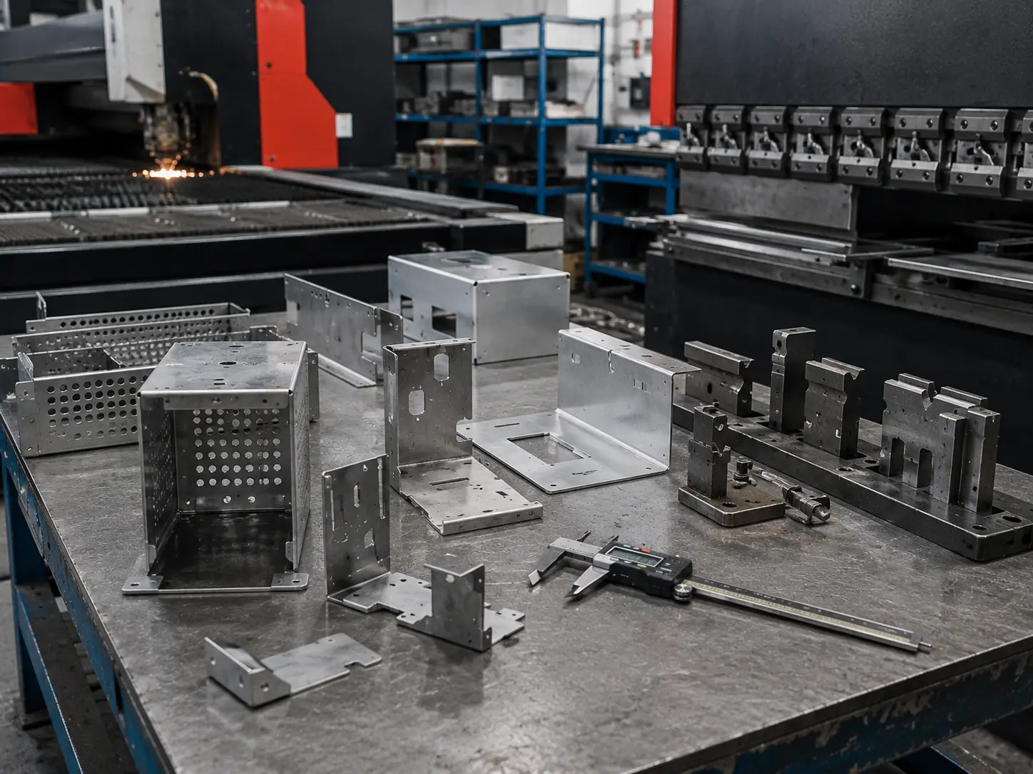
Sheet metal parts produced with minimal dedicated tooling

Ideal for prototypes and low volumes. Highest flexibility with minimal upfront investment, but typically the highest unit cost.

Soft Tooling
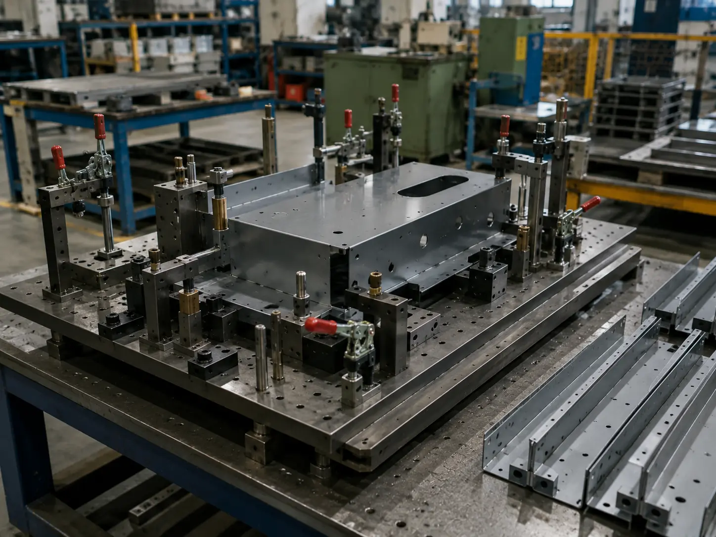
Soft tooling used for medium-volume sheet metal production

Lower investment with relatively quick lead times. A practical option for medium volumes where repeatability matters but full production tooling is not yet justified.

Lower Investment
Higher Unit Cost
Higher Investment
Lowest Unit Cost

CTQ Control & Quality Consistency
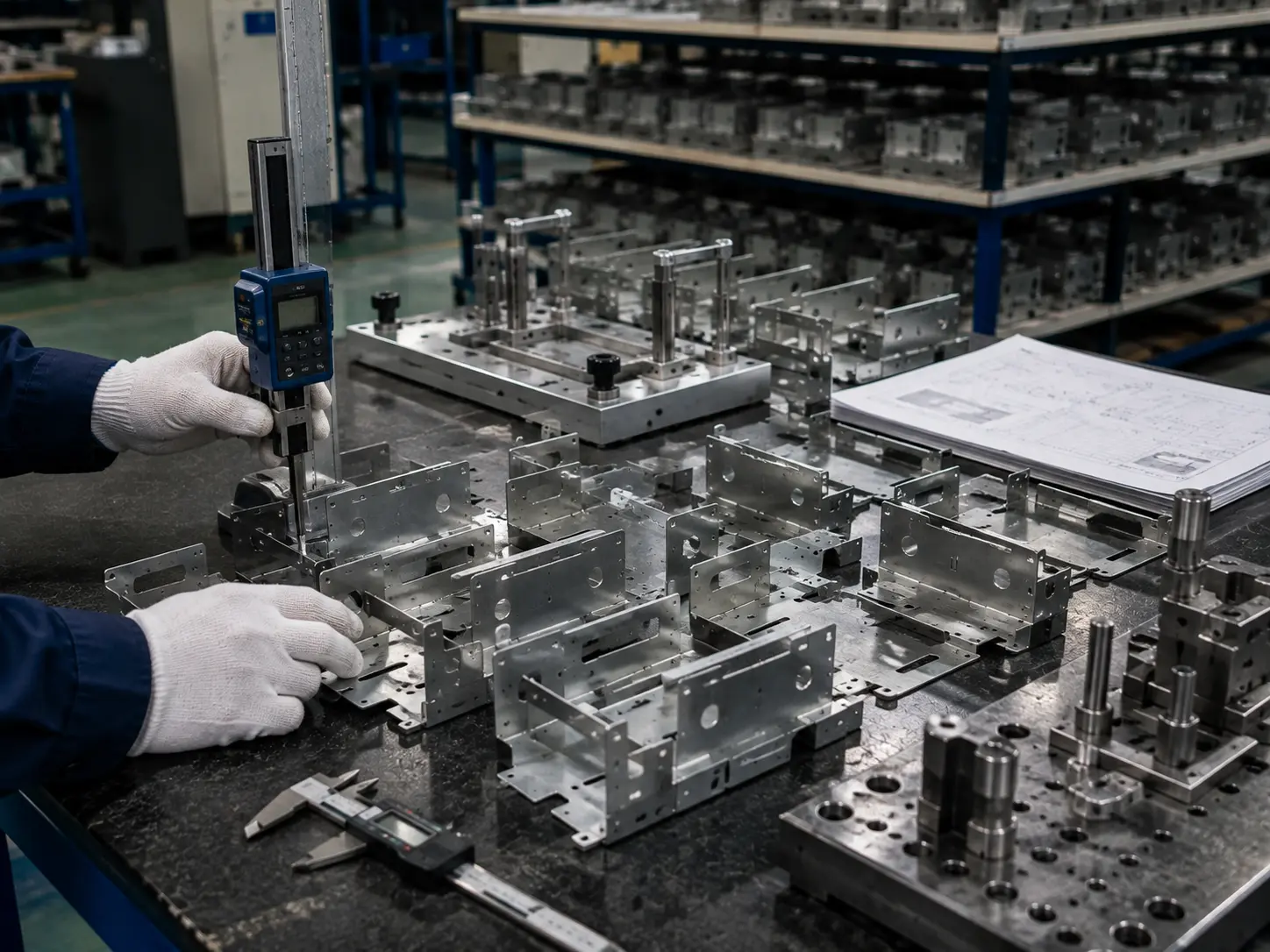
Dimensional inspection of high-volume sheet metal parts during CTQ quality control

Key CTQ Parameters

Bend Angle ±0.5° typical
Hole Position ±0.10 mm
Ebenheit 0.5 mm / 500 mm
Edge Condition Deburr per specification
Oberflächenbehandlung As specified
Cosmetic Scratch & dent control
Wareneingang
Verification
In-Process
Prüfung
Final Dimensional
Inspection (FAI)
Chargenrückverfolgbarkeit
& Records

Cost Breakdown and a Practical Cost-Down Path

In production programs, unit price isn’t driven by any single operation. It’s shaped by Material, cycle time and labor, secondary ops / cosmetic rework, finishing requirements, und fixtures/die investment. Our approach is to break the cost structure down first, then propose a phased cost-down roadmap you can actually execute. DFM (Design for Manufacturability) is a key lever for reducing cost and rework when applied early.

Serienfertigung von Blechbauteilen FAQs 

High volume isn’t just a number—it’s when a program has moved into long-term, repeat supply: the same part runs on a rolling basis, the production cadence is repeatable, and upfront setup/tooling can be amortized over the product’s life. In many industries, hundreds to thousands of repeat parts is a common high-volume context—typically with less flexibility sondern lower unit cost as volume scales.

We usually recommend starting a fixtures/tooling evaluation when you hit one or more of these triggers:

  • Demand shifts into a stable rolling forecast (not a one-off order), and the product life is long enough to justify upfront investment.

  • CTQs (critical-to-quality features) are clearly defined and revision changes slow down—so key datums and key operations can be “locked in” with fixtures or dies.

  • Unit cost is highly sensitive to Zykluszeit, and it becomes worthwhile to integrate multiple operations into a higher-throughput flow (e.g., stamping several features in one press stroke).

We’ll evaluate whether a tooling-based route makes sense based on annual volume, lifecycle, design freeze level, CTQs, and takt/cycle-time targets—rather than forcing a single “threshold number.”

At its core, the “break-even” comes down to whether one-time investment (tooling/fixtures/setup) can be amortized by lifecycle volume—und whether unit labor/cycle time/secondary ops can be materially reduced through process integration. High-volume routes often have higher setup/tooling cost, but lower unit cost—and they’re typically less flexible.

We usually look at five variables:

  • Amortization math: tooling/fixture investment ÷ forecast volume (over the product lifecycle)

  • Process integration: progressive/transfer setups can integrate piercing/forming, cutting cycle time and labor (but reducing flexibility)

  • Changeover efficiency (SMED): reducing changeover from “tens of minutes” toward “minutes” directly impacts OEE and multi-model capability

  • Material yield & scrap structure: nesting/layout and scrap patterns can swing material cost significantly

  • CTQs & tolerance chains: the more sensitive features you have (hole-to-bend, multi-bend stack-ups, assembly datums), the more value there is in “hardening” key relationships with fixtures/dies—or defining a more realistic tolerance window

Yes—we can give an initial route recommendation and a budgetary quote range from 3D (STEP/IGES, etc.). But for an executable production quote and repeatability alignment, we strongly recommend adding a 2D/PDF so tolerances, datums, cosmetic requirements, and process notes are unambiguous.

At minimum, please provide:

  • Werkstoff: spec/standard + thickness + surface condition

  • Tolerance scheme: general tolerances (e.g., ISO 2768) + CTQs called out separately (hole patterns, hole-to-bend, functional faces)

  • Processes & post-processing: welding / inserts / self-clinching hardware / finishing + masking areas

  • Volumes & ramp plan: first build quantity + annual rolling forecast + split-shipment cadence (this drives the process route and tooling strategy)

We recommend aligning on cosmetic grading + standardized acceptance rules:

Cosmetic surface grading

  • A: frequently seen / touched

  • B: visible

  • C: non-visible

Texture / grain direction

  • Specify brushed/grain direction clearly and keep it consistent with viewing and assembly orientation.

Color alignment

  • Use RAL / Pantone / a physical color chip, and agree on viewing conditions (light source, distance, angle). If your system requires tighter control, define an instrumented metric such as ΔE as the acceptance basis.

We prefer CTQs to be defined with datums + a clear measurement method, and flagged as CTQ in the 2D drawing for centralized control.

Recommended callouts:

  • Locating hole patterns: use a datum scheme and define positional relationships (GD&T-style) instead of stacking linear dimensions.

  • Hole-to-bend / across-bend dimensions: state which datum face/edge the measurement is taken from after forming, and distinguish single-bend vs. multi-bend chains (multi-bend stacks compound more easily).

Quick “communication anchors” (for early alignment, subject to review):

  • Bend angle often uses ±1°, cutting features often ±0,2 mm (tighter requires review).

  • Across a single bend: ±0,3 mm; across multiple bends: ±0,5 mm (review-dependent).

It depends on your current route:

Flexible route (laser/turret + bending)

  • Changes are typically handled via program updates—ideal during active iteration before the design is frozen.

Tooling-based route (single-op dies / progressive / transfer)

  • Changes may require die modification and re-tryout, which is more expensive and slower. In practice, we recommend:

    • Freeze assembly hole patterns, datum holes, and key formed features before committing to hard tooling/progressive dies.

    • For “likely-to-change” features, consider modular design areas, or a hybrid approach (stamping + secondary ops) to balance cost and takt time.

    • If frequent changes are expected, stay on laser+bending longer, or use stamping with secondary machining for the moving features.

Yes. To prevent rework and assembly variation at volume, we typically need:

  • Hardware/insert list: part numbers, material/finish, quantity, install side, hole requirements, and install direction

  • Assembly information: assembly drawing/exploded view, key clearances, torque requirements, and acceptance criteria (pull-out/spin-out, if applicable)

  • If blind rivets are involved, we can align to the applicable ISO standard (for example, ISO 15977 covers open-end blind rivets with a break-pull mandrel)

We propose alternatives in this priority order: same function → manufacturable → controlled risk:

  • Closest-grade substitutions within the same family (protecting key needs like corrosion resistance, conductivity, magnetism)

  • Standardized thickness/width to improve availability and nesting yield

  • If needed, thickness/structure compensation (local flanges, ribs) to maintain strength and interfaces

  • After substitution, we recommend a small validation build to confirm forming/springback, finishing compatibility, and assembly performance.

In one line: finishes add build—critical fits should be masked or designed with allowance.

  • Powder coating: typical film build is about 2–5 mil (50–125 μm), which can noticeably affect holes, slip fits, and snap features

  • Anodizing: as a conversion coating, it has dimensional growth both inward and outward (not purely “added on top” like plating)

Recommendation: call out in your 2D notes:

  • finish areas

  • masking areas

  • post-finish requirements for critical fits (holes/threads/grounding surfaces/EMI shielding interfaces)

Yes—and it’s a common, low-risk path for high-volume programs:

  • Phase 1 (validation): laser/turret + bending + only necessary fixtures to validate assembly and CTQs

  • Phase 2 (ramp): key fixtures + cell-based organization to lock takt time and consistency

  • Phase 3 (stable high output): once the design is frozen and demand is stable, evaluate single-op / progressive / transfer dies

This staged-investment approach reflects the basic reality of high-volume manufacturing: setup costs are higher, but can be amortized over a long, stable lifecycle—without betting on hard tooling before the design is truly frozen.